f. Switch the Vertical Display to 2 dB/DIV and adjust the
REF LEVEL so the signal amplitude is half screen. If the
492/492P has Option 01, adjust PEAKING for maximum
response.
g. On the sweep generator, change to the automatic in
ternal sweep (Marker Sweep) and set the sweep time for
1 0 0 s/sweep (its slowest sweep).
h. Activate VIEW A and VIEW B then select a sweep
time on the 492/492P so the stored display is solid (no
breaks in the digitized display, see Fig. 3-37A).
i. Activate MAX HOLD and SAVE A. Trace and record
the response of band 4.
j. Deactivate VIEW A and MAX HOLD (SAVE A and
VIEW B still active).
k. Switch the Vertical Display mode to 10 dB/DIV and
note the baseline. Activate NARROW Video Filter and ad
just the REF LEVEL so the baseline moves to the top of the
screen.
I. Switch the Vertical Display mode to 2 dB/DIV. Activate
VIEW A and adjust the REF LEVEL so SAVE A display and
the baseline are at center screen.
Calibration—492/492P Service Vol. 1 (SN B030000 & up)
Adjustment Procedure
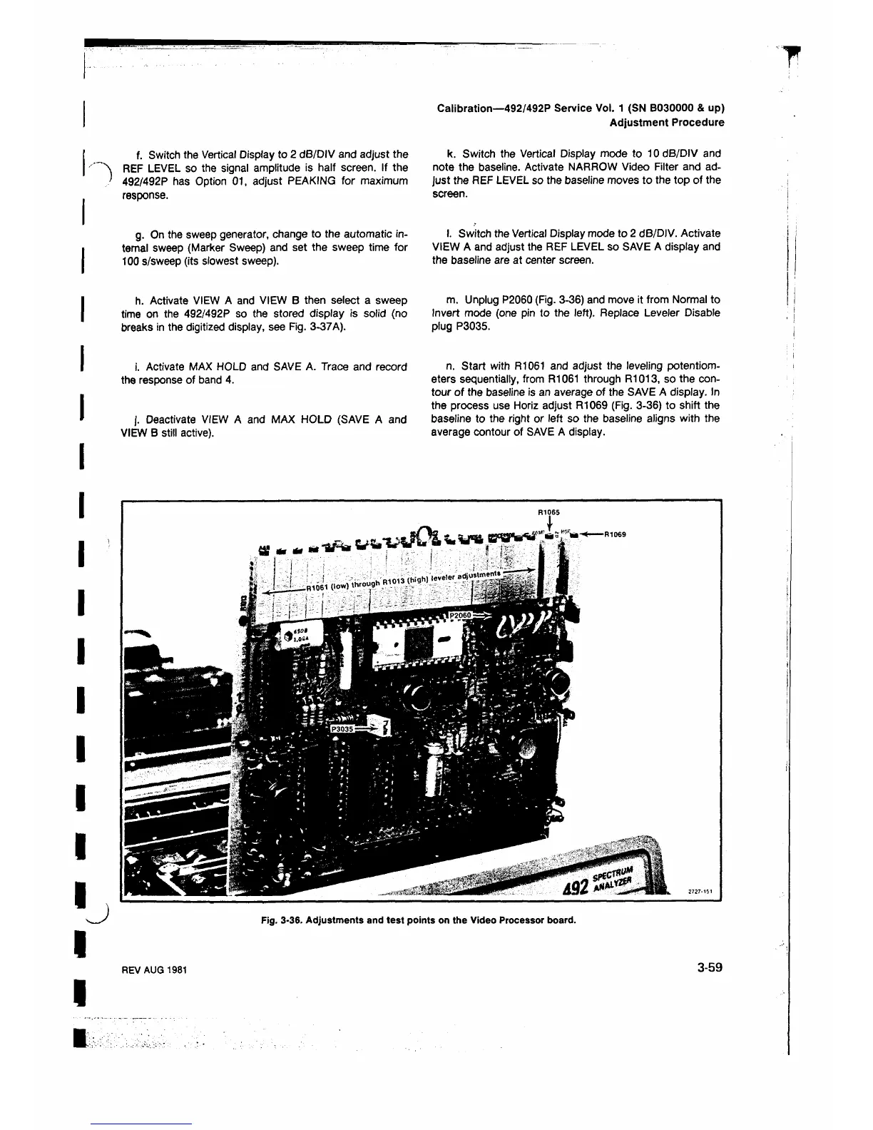
m. Unplug P2060 (Fig. 3-36) and move it from Normal to
Invert mode (one pin to the left). Replace Leveler Disable
plug P3035.
n. Start with R1061 and adjust the leveling potentiom
eters sequentially, from R1061 through R1013, so the con
tour of the baseline is an average of the SAVE A display. In
the process use Horiz adjust R1069 (Fig. 3-36) to shift the
baseline to the right or left so the baseline aligns with the
average contour of SAVE A display.
Fig. 3-36. Adjustments and test points on the Video Processor board.
REV AUG 1981
3-59
 Loading...


