r
3) turn Compensation adjustment R1065 counterclock
wise until the display breaks up (see Fig. 3-38B);
4) now turn R1065 clockwise 1.5—2 turns past the
point the display again becomes a periodic triangular
waveform;
5) turn Horiz adjust R1069 to center the display;
6 ) return the baseline leveler adjustments to their
midrange position for a straight line display and proceed
with the baseline leveling alignment as previously de
scribed (parts a through q).
9. Log Amplifier Calibration
> CAUTION <
Use only an insulated screwdriver or tuning tool, such
as Tektronix Part No. 003-0675-00, to make these
adjustments.
Calibration—492/492P Service Vol. 1 (SN B030000 & up)
Adjustment Procedure
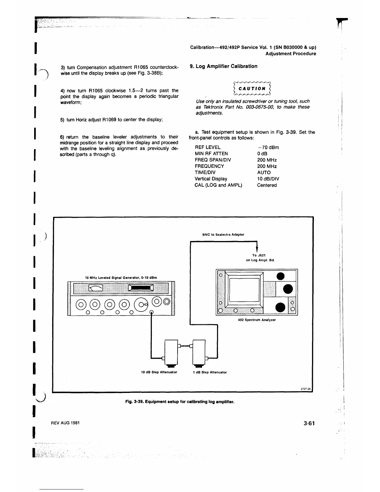
a. Test equipment setup is shown in Fig. 3-39. Set the
front-panel controls as follows:
REF LEVEL
MIN RF ATTEN
FREQ SPAN/DIV
FREQUENCY
TIME/DIV
Vertical Display
CAL (LOG and AMPL)
-7 0 dBm
OdB
200 MHz
200 MHz
AUTO
10 dB/DIV
Centered
J
BNC to Sealectro Adapter
Fig. 3-39. Equipment setup for calibrating log amplifier.
REV AUG 1981
3-61
u
 Loading...


