Calibration—492/492P Service Vol. 1 (SN B030000 & up)
Adjustment Procedure
b. Remove P621 and apply a 10 MHz signal of 0 dBm
from the signal generator, through 10 dB and 1 dB step
attenuators, to the input of the Log Amplifier at J621 (Fig.
3-40). Set the step attenuators for 50 dB of attenuation.
g. Alternately switch the Vertical Display between
10 dB/DIV and 2 dB/DIV while adjusting Input Ref Lvl,
R4071 (Fig. 3-40), for minimum amplitude change between
the two displays.
c. Position the display at a graticule reference line with
the variable output of the signal generator; then switch the
REF LEVEL from -70 dBm to -120 dBm, and adjust the
front panel LOG CAL so each 10dB step equals one
division.
d. Set the REF LEVEL to —20 dBm and the attenuators
for 0 dB.
h. Switch Vert Display to 2 dB/DIV. Switch in 10 dB of
attenuation and note how close the 10 dB step is to five
divisions of display change. If the 10 dB step is short (trace
falls short of the correct line), adjust gain with R4020 slightly
in the same direction; then switch out the 10 dB of attenu
ation and adjust R1071 for a full screen display. Repeat this
check until the 10 dB step is within 0.2 dB. Switch to
10 dB/DIV display mode and recheck 10 dB logging.
e. Increase the step attenuators in 10 dB steps. Adjust
Log Gain, R4020 (Fig. 3-40), so each 10 dB of change pro
duces a division of change on the display.
i. Switch to the 2 dB/DIV mode; then momentarily re
move the input signal to the Log Amplifier and position the
display on the bottom graticule line. Re-apply the signal to
the Log Amplifier.
f. Return the step attenuator to 0 dB. Display should be J. Adjust Output Ref Lvl, R4081 (Fig. 3-40), for a full
full screen (0 dBm); if not, readjust the signal generator out- screen (eight divisions) display,
put for 0 dBm.
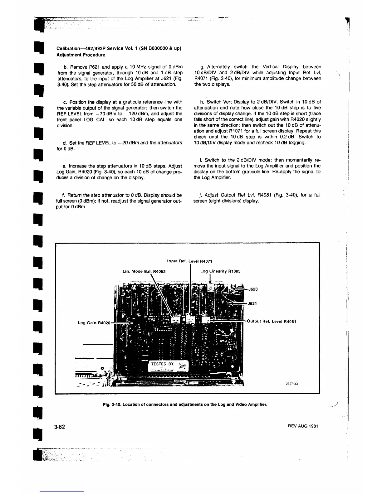
Input Ref. Level R4071
Lin. Mode Bal. R4052
■ J620
-J621
Output Ref. Level R4081
Fig. 3-40. Location of connectors and adjustments on the Log and Video Ampiifier.
3-62
REV AUG 1981
 Loading...


