Calibration—492/492P Service Vol. 1 (SN B030000 & up)
Adjustment Procedure
10 MHz Signal Source
I O
CS f ij g
/ J j68
BNC to Sealectro Adapter
© @ © @ ( ^ ® °
ο Ο ο Ο ^ Φ
■
VR
J68?
/
t Module1
: V
X
J 6 8 2
a
To J621 of log Ampl.;
O O P
492 Spectrum Analyzer
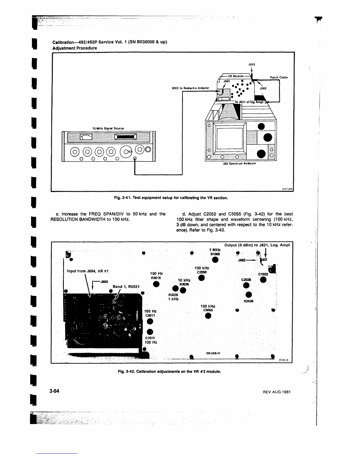
Fig. 3-41. Test equipment setup for calibrating the VR section.
c. Increase the FREQ SPAN/DIV to 50 kHz and the
RESOLUTION BANDWIDTH to 100 kHz.
d. Adjust C2050 and C5055 (Fig. 3-42) for the best
100 kHz filter shape and waveform centering (100 kHz,
3 dB down, and centered with respect to the 10 kHz refer
ence). Refer to Fig. 3-43.
1 MHz
R1065
Output (0 dBm) to J621, Log. Ampl.
Input from J684, VR #1
■ J683
100 kHz
C2Q50
10 kHz
R3035
· ·
R3025
1 kHz
100 kHz
C5055
• ...
J682-
I
- fee
C1022
C2026 Λ
4
R2038
Fig. 3-42. Calibration adjustments on the VR #2 module.
3-64
REV AUG 1981
 Loading...


