Calibration—492/492P Service Vol. 1 (SN B030000 & up)
Adjustment Procedure
Θ. Return the RESOLUTION BANDWIDTH to 10 kHz
and recheck for centering. Switch the FREQ SPAN/DIV to
500 kHz and the RESOLUTION BANDWIDTH to 1 MHz.
f. Adjust C2026 and C1022 (Fig. 3-42) for the best
1 MHz filter shape and waveform centering.
g. If the instrument has Option 03 (100 Hz filter) switch
the RESOLUTION BANDWIDTH to 100 Hz and FREQ
SPAN/DIV to 500 Hz.
h. Adjust the 100 Hz filter shape and response ampli
tude with C6011 and C7011. Adjust for maximum amplitude
and a bandwidth, at the 3 dB down point, of 100 Hz.
i. Now disconnect the 10 MHz third converter signal
(P693) from the VR#2 input and connect it to the input of
VR#1 (J693), through the Sealectro male-to-male adapter
and coaxial cable. Connect the output of VR#1 (P683)
through another Sealectro male-to-male adapter and co
axial cable to the input of the Log Amplifier at J621 (Fig.
3-40).
j. Change the FREQ SPAN/DIV to 500 kHz and RESO
LUTION BANDWIDTH to 100 kHz. Readjust the REFER
ENCE LEVEL for a seven division signal in the 2 dB/DIV
display mode.
k. Switch the FREQ SPAN/DIV to 10 kHz and the RES
OLUTION BANDWIDTH to 10 kHz. Center the response on
screen.
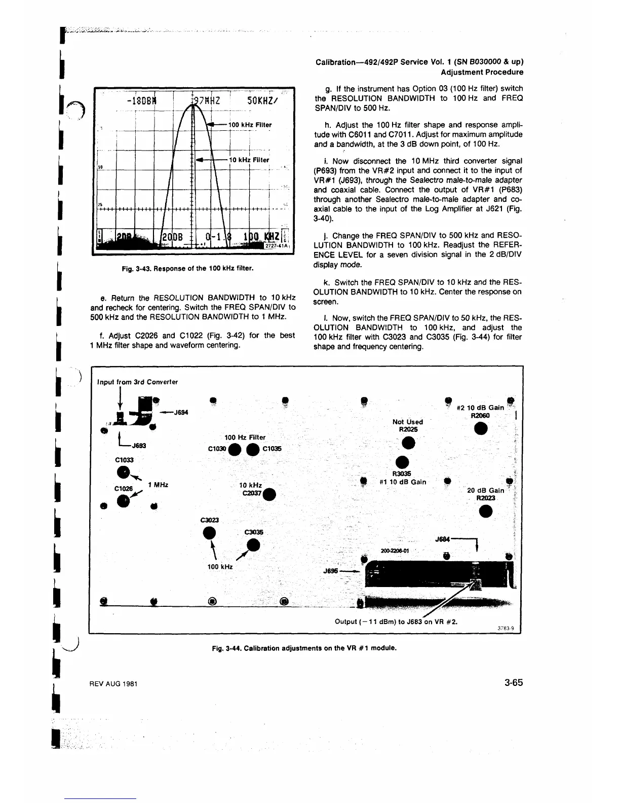
I. Now, switch the FREQ SPAN/DIV to 50 kHz, the RES
OLUTION BANDWIDTH to 100 kHz, and adjust the
100 kHz filter with C3023 and C3035 (Fig. 3-44) for filter
shape and frequency centering.
Input from 3rd Converter
I»
I
J L
L
Λ
-J694
-J693
C1033
100 Hz Filter
C1030 φ φ C1035
1 MHz
10 kHz
0 2 0 3 7 φ
C3023
C3035
I S
100 kHz
S l
m
<§>
9
Not Used
R2025
m &
? #2 10 dB Gain "
R2060 |
R3035
• #110 dB Gain
20 dB Gain
R2023
J684-
J695-
Output ( -1 1 dBm) to J683 on VR #2.
3783-9
Fig. 3-44. Calibration adjustments on the VR # 1 module.
REV AUG 1981
3-65
 Loading...


