Brief procedures
8. Set the oscillo
scope as follows:
a. Vertical scale: 200 mV/div (CH 1), 1 V/div (CH 2 and CH 3)
b. Horizontal scale: 20 ns/div
c. Input coupling: DC
d. Input impedance: 50 Ω
e. CH 1 position: +2 div (if necessary)
f. CH 2 positi
on: –1 div (if necessary)
g. CH 3 position: –3 div (if necessary)
h. Trigger source: CH1
i. Trigger level: 0 mV
j. Trigger slope: Positive
k. Trigger mode: Auto
9. Press t
he Home button on the instrument, or click the Home tabonthedisplay.
10. Click the Reset to default setup button in the toolbar.
11. On the instrument, load the PV_Square.wfmx waveform as an output
waveform. Follow the steps below:
a. In the Waveform List window, click Open Waveform and navigate to
C:\Program Files\Tektronix\AWG70000\Samples\PV.
b. Select Open File.
c. In the Waveform List window, select (drag and drop) the
PV_Square.wfmx waveform on to the work space.
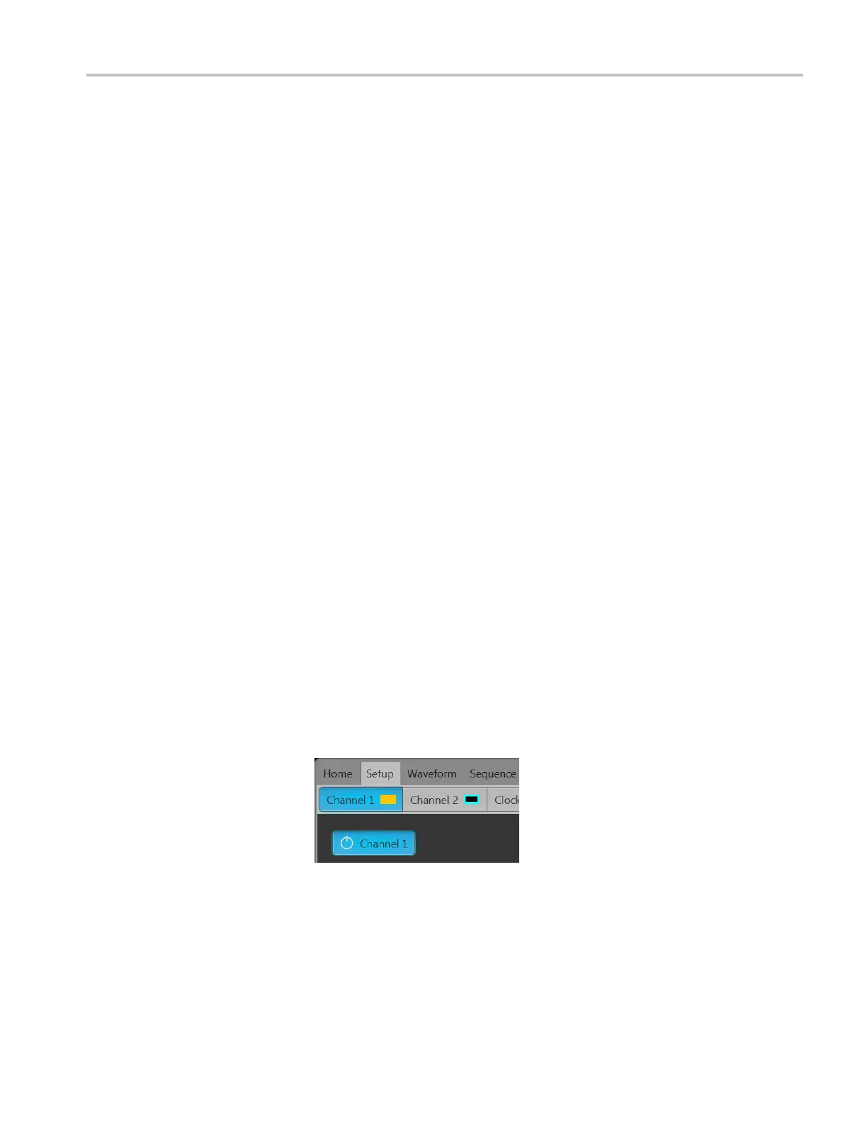
12. In the Setup tab, under Resolution, check 8+2 Mkrs.
13. Click the Enable outputs button.
14. Click the Play button on-screen or on the instrument.
15. Press the All Outputs button on the instrument to output the waveform.
16. Check that the Channel 1, Marker 1, and Marker 2 waveforms are properly
displayed on the oscilloscope screen. (See Figure 2-5.)
AWG70000A Series and AWGSYNC01 Technical Reference 2–11

 Loading...