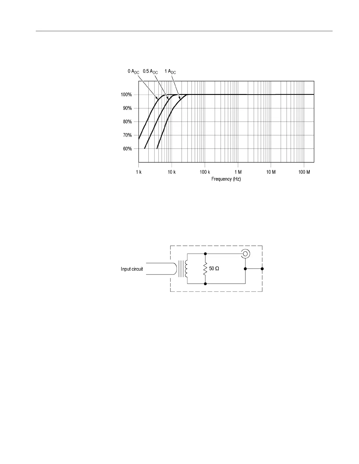
Description
This response w
as obtained with the + side of the CT-2 facing the signal source
(preferred connection).
Figure 3
: CT-2 frequency response vs. DC current
The CT-1
and CT-2 consist of a current transformer and a flexible probe cable that
attaches between the transformer and the oscilloscope. In addition, the CT-1 and
CT-2 have an internal termination resistor that reduces reflections that allows the
transformer to be disconnected from the probe cable and left in the circuit. The
following figure shows a simplified circuit of the CT-1 and CT-2.
Figure 4: CT-1 and CT-2 simplified circuit
CT-1 and CT-2 Current Transformer Instructions 3