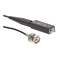
Operation
If the CT-1 or CT
-2 is connected so that the positive (+) label side faces the signal
source, the input current and output voltage are in phase. This is the preferred
connection. For pulses with a risetime slower than 1 ns, the CT-1 or CT-2 may be
connected in either polarity.
The voltage on the signal wire must be limited to 30 VAC or 42 Vpk. Voltage
ratings apply to insulated and non-insulated conductors.
WARNING. To reduce risk of electric shock, us e only insulated conductors with
these probes on circuits with voltages above 30 VAC or 42 Vpk. These probes are
not rated f
or bare wire voltages above 30 VAC or 42 Vpk.
WARNING. To reduce risk of electric shock and fire, do not connect or disconnect
the curr
ent probe to the DUT with the circuit energized. The metal stud and
output terminal are not insulated. Always remove power before you c onnect or
disconnect the CT-1 or CT-2 to or from the DUT.
NOTE. An insulated conductor is any conductor that is surrounded by an
insulating material that is capable of isolating the voltage present on the
conductor. Lacquer c oatings like those typically found on transformer windings
do not provide sufficient, reliable insulation f or use with current probes. The
lacquer coating can be easily nicked or damaged, which compromises the
insu
lating capabilities of the lacquer coating.
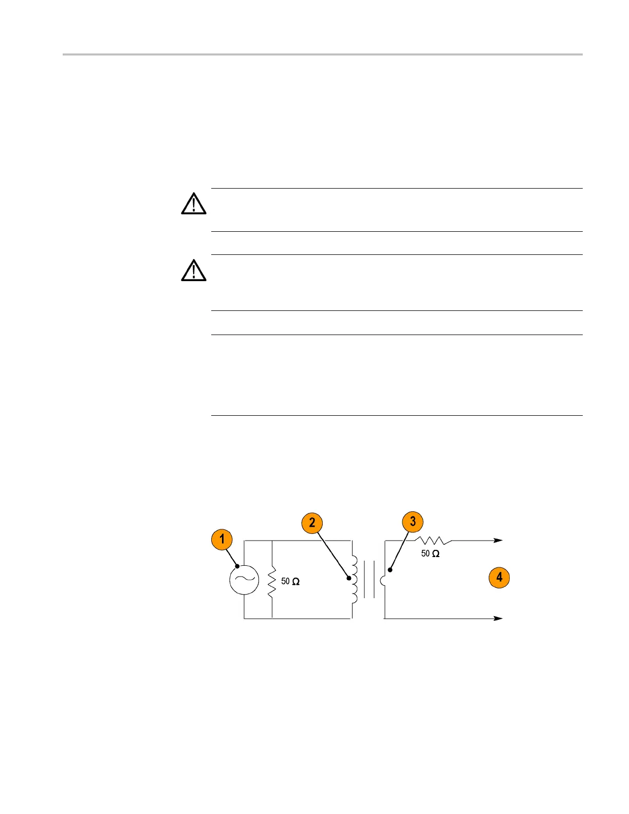
Injecting Current Signals
When injecting AC current into a single conductor, the current probe acts as the
primary winding and the conductor acts as the secondary winding of a transformer.
1. Signal generator
2. Current probe primary
3. Circuit under test (secondary)
4. To circuit under test
CT-1 and CT-2 Current Transformer Instructions 5