Operation
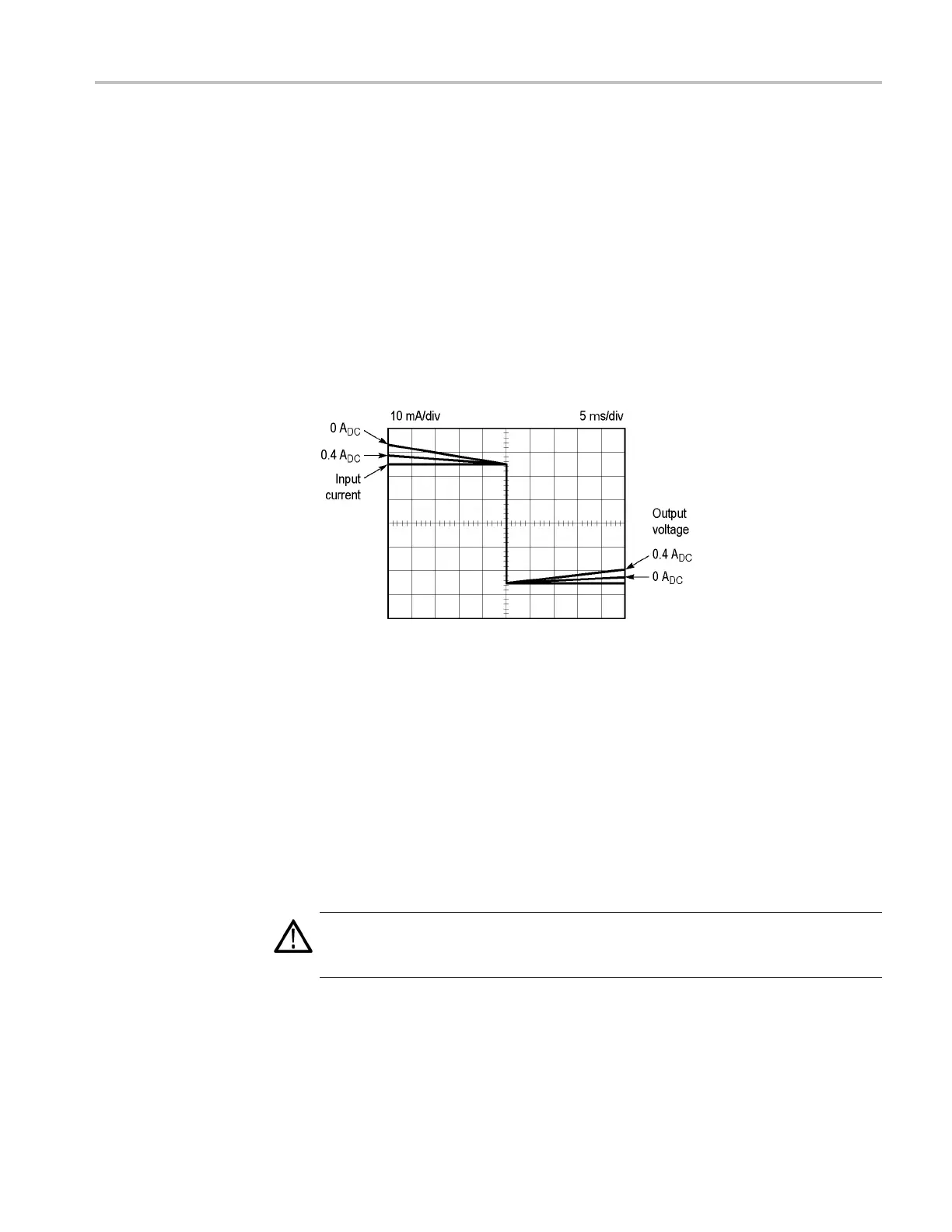
When droop is pr
esent at low frequencies, the apparent overall peak-to-peak
height from top to bottom is not the true current. The height of a fl at-top pulse still
can be measured accurately by observing the transition edge of the pulse. The
50 mA pulse is faithfully reproduced at the high-to-low transition at the center
of the screen. (See Figure 7.)
Pulse width, tilt, and the lower 3 dB frequency are related by the formula:
Percent tilt = 200π Tp f
1
Where:
Tp = pulse w
idth
f
1
= l ower 3 dB frequency
Figure 7: CT-2 decay characteristics referenced to transition
Additional consideration needs to be given to the amp-second rating of the
tran
sformer. The product of the pulse current and the pulse duration should be less
than the amp-sec ond ra ting to kee p the transformer core from saturating. When
saturation occurs, the output voltage falls to zero.
Probe Handling
Only normal handling considerations are necessary with the CT-1 and CT-2
transformers. They are sealed units and are not designed to be disassembled. If
the transformer or cable is damaged, return it to Tektronix for replacement.
CAUTION. Dropping the CT-1 or CT-2 transformer may break the probe. Do not
p
ull or stretch the P6041 cable or place objects on the cable. This may damage
the probe cable.
CT-1 and CT-2 Current Transformer Instructions 7