Operating
Instructions
—
DM
501A
r
CAUTION
<
T-i
help eliminate shock
hazard
from
voltages
measured
by
the DM 501 A:
1
If the measured voltage exceeds 42.5
V
peak,
avoid all contact
with
the voltage source.
2
Disco/aioU test probes from circuit-under-test
before disconnecting probes from
the
DM
501 A,
or
before removing the DM
501 A
from the power
mrdu'e.
Do
Vo'tage Measurements
Ptosj. t^s VOLTS DC push
button and an appropriate
rnnno hu'ton. Apply the voltage to be
measured
to
the
I
'
:\d VO't TS/Q
Input connectors. Observe the
max-
imum
ifipu*
'/ullage
ratings
as
indicated on the front
panel.
Ih:; ru.adou’ displays a
!
reading if
the input
to
the
V(.;'
I hdi'l connector is
positive with respect
to
the LOW
input connector.
A
-
reading
>5
displayed
if
the input at the
VO!
T
S^n connector
is more
negative. With the LOW
and
VTM'IS/O input connectors
shorted, the display
reads
zero
O';
to
U*o
specifications.
Dc Current
.Measurements
Pi
ess
tlie
rnA DC push button and appropriate range
button. Connect
the
dc
current to be
measured tothe LOW
and mA
input connectors.
Conventiof^a! current
flowing
into tfie mA
connector and out of the
LOW connector
indicc'tes
a
I
on the
display. The current
input
is
protected
vdth an
into’
rial
fuse
located on the
circuit
board.
Refer
to
quaiificcl
personnel
whe-n checking
this fuse.
Ac
V'cltage
and
d8 Measurements
Tor
ac voltage
measurements, press
the VOLTS
AC
push button and an
appropriate range
button.
Connect the
unknown voltage
between the LOW
and VOLTS/Q
input
connectors. The ac
voltage and dB
measurements
are
made
with
an ac
only calculating
true rms to dc
converter.
Vo'taqos
can be measured
with
a crest
factor up to
four.
The crest
factor is ttie
ratio
of
the peak
voltage to
rms
voltage.
Press the VOLTS
AC and
dB push
buttons with an
appropria'o
range button.
A
.120 dB dynamic
rangeexists
v/hen
any
one
range
pusfi button is
pressed, except
in the
! 40
(‘3
range, T
fie dE?
rneosuremont is
obtained by
adding
the
rUcphycd value to
the
selected range. For
example, a
I5.G
(iisplayed
reading
on the 20
dB range
cor-
rospo.nds
to
a 35,6
dB
signal. When
in the
I
40
dB range,
ttic maximum
displayed
value
must be
limited to
i
16.2 dBm
or
!
14
dBV
because
of
the
500
Vacmaximum
rating
of
tt'C
iristriirnent.
When
the
DM
501A is shipped, the
0
dB reference
is
1 mW into 600
Q
(0./746
V).
A
0 d 3
reference
of
1
V
is also
available through an internal
jumper (see the Calibration
Procedure).
Refer /umper
change to qualified personnel.
Ac Current Measurements
To measure
ac
current,
press
the
mA push
button
and
an appropriate range button. Connect
the unknown
ac
current to be measured between the
mA and LOW input
connectors. The
ac
current measurements
are made using
an ac only calculating true rms to
dc
converter.
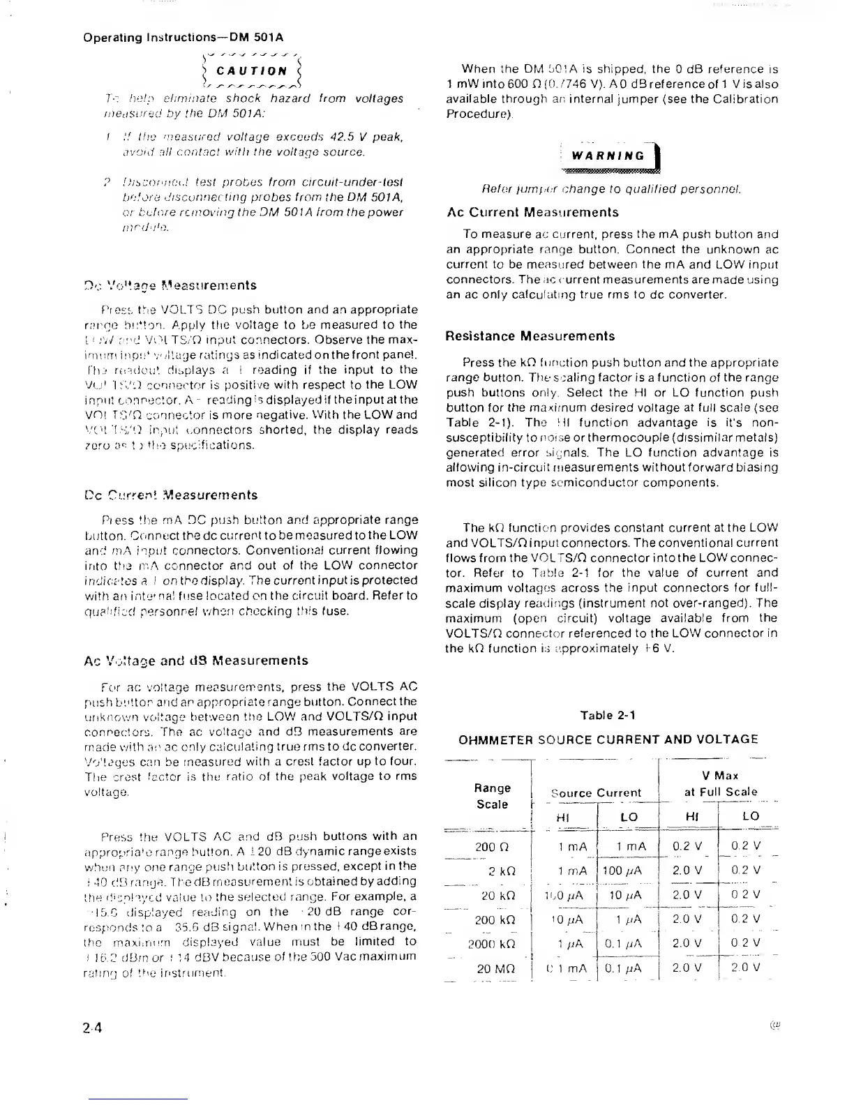
Resistance Measurements
Press the
kQ
function
push button and the
appropriate
range button. Ttie scaling factor is
a
function
of
the range
push buttons only Select the HI or LO function push
button for the maximum desired voltage
at
full scale (see
Table 2-1). The HI function advantage is
it's
non-
susceptibility
to
noise or thermocouple
(dissimilar
metals)
generated
error signals.
The LO
function
advantage
is
allowing
in-circuit
measurements
withouttorward biasing
most silicon type
semiconductor
components.
The kQ function provides constant current
at the LOW
and VOLTS/n input connectors. The conventional
current
flows
from
the VOLTS/0 connector intothe LOW connec-
tor. Refer
to
Table
2-1
for the value
of current and
maximum voltages across the
input connectors for full-
scale display
readings (instrument not over-ranged). The
maximum
(open circuit) voltage available from
the
VOLTS/n
connector referenced to the LOW
connector in
the kQ
function Is c.pproximately
1-6
V.
Table
2-1
OHMMETER
SOURCE
CURRENT AND
VOLTAGE
Range
Scale
Source
Current
V
Max
at
Full Scale
I
HI
LO
HI
LO
200 n
1 mA
1 mA
iLOy/A
1
mA
0.2 V
0.2
V
0.2 V
2
kQ
1
00
pA 2.0 V
20
kO
200 kO
'
2000
kQ
'
20 MQ
fOpA 2.0 V
I
0 2V
10 yjA
1
pA
1
pA
0.1
pA
2.0 V
2.0 V
0.2 V
0 2
V
0 1 mA
j
0.
1 M
2.0
V
I
2.0 V
 Loading...


