Front-Panel Operation
Controls and Indicators 3
3-7
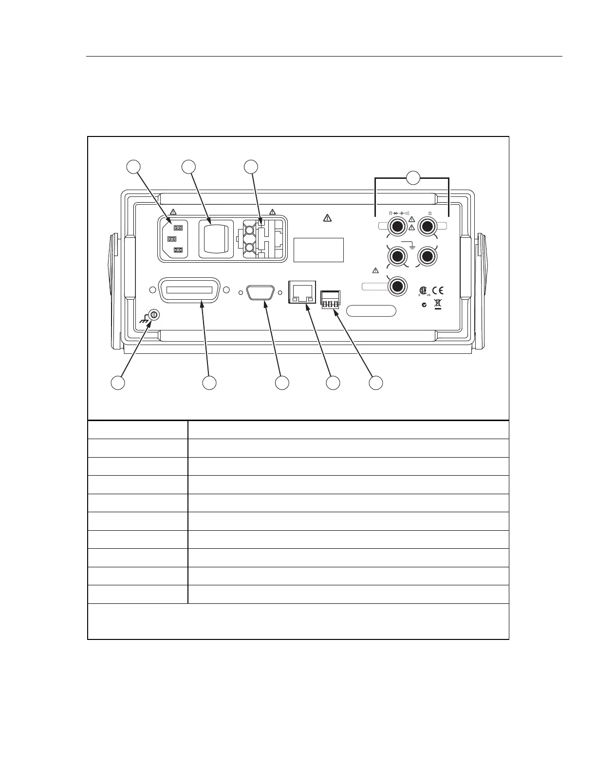
Rear-Panel Connectors
Table 3-3 indicates the connections on the rear panel and describes their use.
Table 3-3. Rear-Panel Connectors
TRIG I/O
IEEE488
RS-232
LAN
TEKTRONIX CORPORATION
Assembled in USA
www.tektronix.com
400 mA
CAUTION:
FOR FIRE PROTECTION REPLACE
ONLY WITH A 250V FUSE
AS STATED IN MANUAL.
NO INTERNAL USER SERVICEABLE PARTS
REFER SERVICE TO QUALIFIED SERVICE PERSONNEL
WARNING:
TO AVOID ELECTRIC SHOCK
GROUNDING CONNECTOR
IN POWER CORD
MUST BE CONNECTED
CAL STICKER
SERIAL TAG
1
/
4
A SLOW FUSE,100/120 VAC
1
/
8
A SLOW FUSE, 220/240 VAC
47 - 440 Hz
25 VA MAX
1000 V CAT I
600V CAT II
INPUT SENSE
4
W
FUSED
1V
300V
V
1 2 3
56789
4
N60
LOLO
HI HI
LR44340
gdc05.eps
Item Description
A Line Power Cord connector
B Power Switch
C Fuse holder and power line voltage selector
D Rear-panel input connectors
[1]
E External trigger input and measurement complete output port
F Ethernet (LAN) connector
G RS-232 connector. See appendix C for signals available on this connector.
H IEEE 488 (GPIB) connector
I Ground connector
Notes:
[1] 10 A current measurements can not be performed through the rear-panel connectors

 Loading...


