Performance Verification
d. Calculate V
diff
=V
pos
–V
neg
, and then enter V
diff
in the test record. As an
example, on the 5 mV/div setting, if V
pos
is 17.4 mV and V
neg
is -17.2
mV, then V
diff
is 34.6 mV.
e. Enter V
diff
in the worksheet, and in the test record.
Table 11: DC Gain Accuracy Worksheet
DC voltage source setting
Volts/div
setting Positive Negative V
pos
V
neg
V
diff
Accuracy limits
for V
diff
5 m V/div
+17.5 mV –17.5 mV 33.6 mV to 36.4 mV
200 mV/div
+700 mV –700 mV 1.358 V to 1.442 V
Channel 1
2V/div
+7.00 V –7.00 V 13.58 V to 14.42 V
5 m V/div
+17.5 mV –17.5 mV 33.6 mV to 36.4 mV
200 mV/div
+700 mV –700 mV 1.358 V to 1.442 V
Channel 2
2V/div
+7.00 V –7.00 V 13.58 V to 14.42 V
5 m V/div
+17.5 mV –17.5 mV 33.6 mV to 36.4 mV
200 mV/div
+700 mV –700 mV 1.358 V to 1.442 V
Channel 3
1
2V/div
+7.00 V –7.00 V 13.58 V to 14.42 V
5 m V/div
+17.5 mV –17.5 mV 33.6 mV to 36.4 mV
200 mV/div
+700 mV –700 mV 1.358 V to 1.442 V
Channel 4
1
2V/div
+7.00 V –7.00 V 13.58 V to 14.42 V
1
Channels 3 and 4 are only on four channel oscilloscopes.
10. Set the DC voltage source to 0 V, a nd move the BNC cable to the next
channel to be tested.
11. Repeat steps 5 through 10 for each remaining channel.
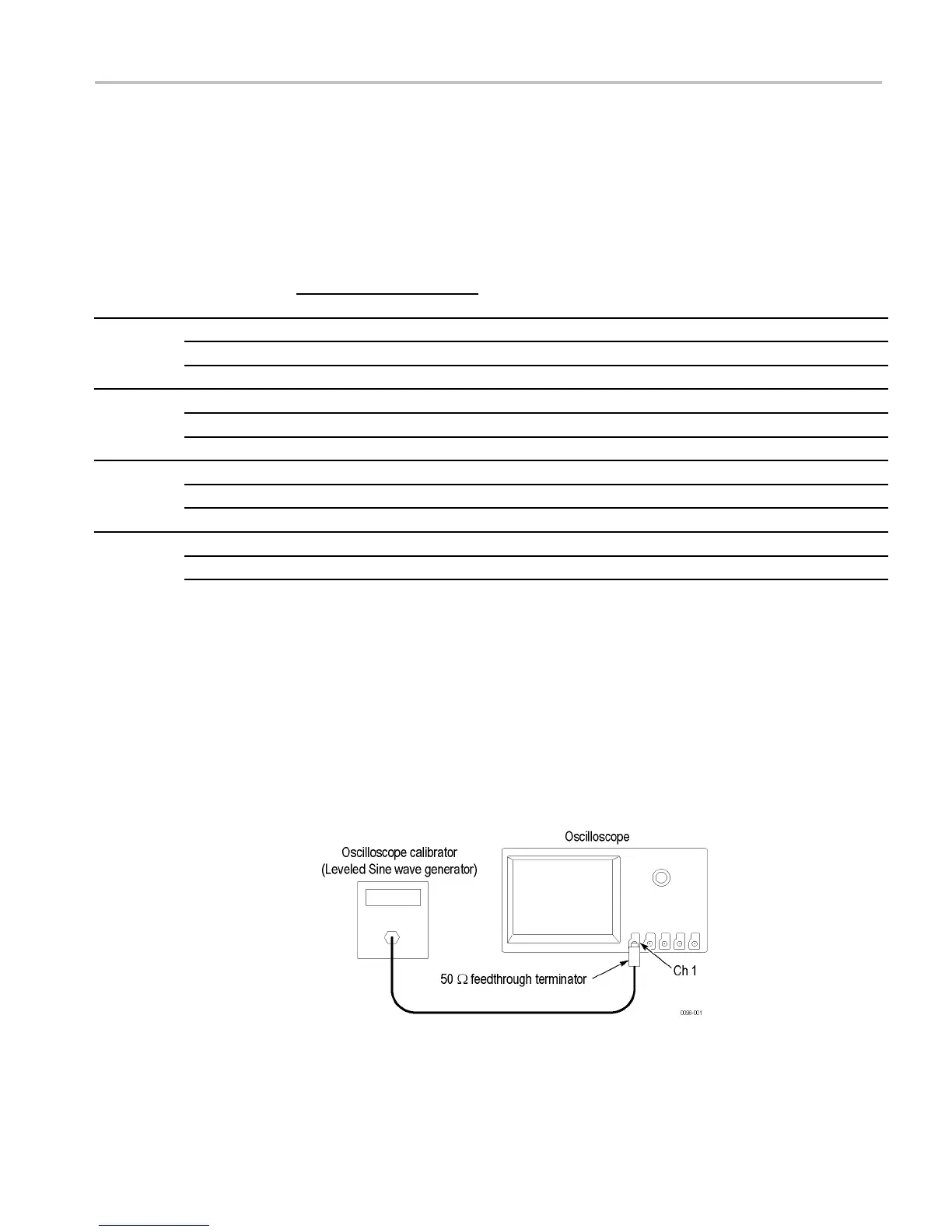
Check Bandwidth
This test checks the bandwidth of all input channels.
1. Connect the output of the leveled sine wave generator (for example, Fluke
9500) to the oscilloscope channel 1 input as shown below.
2. Push the front-panel Default Setup button to set the instrument to the factory
default settings.
DPO2000 and MSO2000 Series Specifications and Performance Verification 21

 Loading...