EasyManua.ls Logo

Tektronix DPO4104 User Manual

Tektronix DPO4104
359 pages
To Next Page IconTo Next Page
To Previous Page IconTo Previous Page
Page #141 background imageLoading...
Page #141 background image
Acquire the Signal
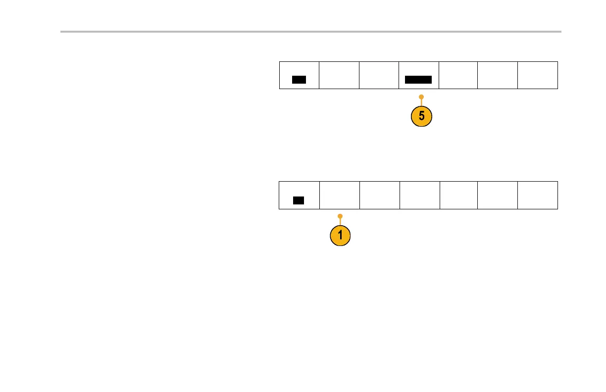
5. Push Bit Rate and turn multipurpose knob a to
select from the list of predened bit rates.
Bus
CAN
Dene
Inputs
Thresholds B it Rate
500 Kbps
B1 Label
CAN
Bus Display Event Table
Alternately, you can set the bit rat e to a specic
value. To do so, select Custom, and then turn
multipurpose knob b to set the bit rate from
10,000 to 1,000,000.
To acquire data from a LIN bus, you need to also set up the se items:
1. If you selected LIN , push Dene Inputs and
the appropriate side-bezel menu choices.
Bus
LIN
Dene
Inputs
Thresholds
Congure
B1 Label
LIN
Bus Display Event Table
MSO4000 and DPO4000 Series Oscilloscopes User Manual 115

Table of Contents

Other manuals for Tektronix DPO4104

Question and Answer IconNeed help?

Do you have a question about the Tektronix DPO4104 and is the answer not in the manual?

Tektronix DPO4104 Specifications

General IconGeneral
BrandTektronix
ModelDPO4104
CategoryTest Equipment
LanguageEnglish

Summary

General Safety Summary

To Avoid Fire or Personal Injury

Essential safety guidelines for operation and handling to prevent harm.

Installation

Operating Considerations

Environmental, power, and physical requirements for instrument operation.

Powering On the Oscilloscope

Procedure for powering up the instrument and ensuring proper grounding.

Connecting Your Oscilloscope to a Computer

Methods for PC connectivity for data transfer and remote control.

Front-Panel Connectors

Front-Panel Connectors

Description of connectors located on the front panel of the instrument.

Rear-Panel Connectors

Description of connectors located on the rear panel of the instrument.

Acquire the Signal

Setting Up Analog Channels

Procedure for connecting and configuring analog input channels.

Using Autoset

Quick method for automatic instrument configuration for optimal signal display.

Setting Up a Serial or Parallel Bus

Configuring bus analysis, triggering, and display parameters.

Setting Up Digital Channels

Configuring digital input channels for mixed-signal analysis.

Trigger Setup

Choosing a Trigger Type

Selecting the appropriate trigger mode for specific signal events.

Selecting Triggers

Detailed configuration of various trigger conditions and parameters.

Triggering on Buses

Specialized triggering for serial and parallel communication protocols.

Starting and Stopping an Acquisition

Procedures for initiating and halting the data capture process.

Display Waveform Data

Setting the Display Style and Persistence

Adjusting waveform appearance, including decay and persistence.

Scaling and Positioning a Waveform

Adjusting the waveform's horizontal and vertical display parameters.

Setting Input Parameters

Configuring channel coupling, impedance, and bandwidth settings.

Analyze Waveform Data

Taking Automatic Measurements

Performing automated measurements of signal parameters.

Taking Manual Measurements with Cursors

Using on-screen markers for precise manual measurements.

Using Math Waveforms

Creating custom analysis waveforms from calculations.

Using FFT

Analyzing signal frequency domain characteristics.

Using Wave Inspector to Manage Long Record Length Waveforms

Tools for navigating and analyzing long data captures.

Application Examples

Taking Simple Measurements

Performing basic signal analysis for amplitude and frequency.

Analyzing Signal Detail

Techniques for examining noisy signals using Peak Detect.

Capturing a Single-Shot Signal

Acquiring fast, transient events for detailed analysis.

Troubleshooting Circuits Using Parallel Buses

Practical example for analyzing parallel bus signals.

Troubleshooting an RS-232 Bus

Practical example for analyzing RS-232 signal integrity.

Related product manuals