Do you have a question about the Tektronix DPO4000 Series and is the answer not in the manual?
Explains symbols and terms used in safety warnings.
Details substances restricted in the product according to RoHS.
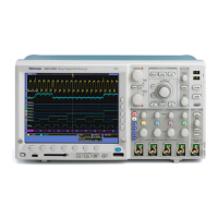
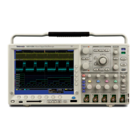
Lists the main capabilities and specifications of the DPO4000 Series oscilloscopes.
Lists other documents available for the oscilloscope and how to access them.
Explains icons and conventions used throughout the manual.
Guidance on unpacking and checking oscilloscope accessories.
Specifies operating environmental and physical parameters for the oscilloscope.
Details how to connect different types of probes to the DPO4000.
Instructions for connecting power and grounding the oscilloscope safely.
Steps to safely disconnect power from the oscilloscope.
Procedure to verify the oscilloscope is operating correctly after setup.
Guide on how to match a passive probe to the oscilloscope's input channel.
Instructions for installing optional software modules to extend oscilloscope functionality.
Steps to change the language displayed on the oscilloscope's interface.
Procedure to set the oscilloscope's internal clock to the current date and time.
Corrects DC inaccuracies caused by temperature variations or long-term drift.
Instructions for updating the oscilloscope's firmware to the latest version.
Explains methods for connecting the oscilloscope to a computer for data transfer and control.
How to access the oscilloscope remotely via a web browser.
Overview of the front panel buttons and controls for accessing functions.
Description and location of various connectors on the front panel.
Details the ground strap connector on the side panel of the instrument.
Identifies and describes the connectors located on the rear panel of the oscilloscope.
Guide on connecting probes and setting up the oscilloscope to acquire signals.
Restores the oscilloscope to its factory default settings.
Automatically adjusts acquisition, horizontal, and trigger controls for a stable display.
Explains the fundamental concepts of signal acquisition and sampling.
Procedure to modify acquisition modes (e.g., Sample, Average) and record length.
Steps to configure triggering and display for serial buses like I2C, SPI, and CAN.
Explains the fundamental concepts of trigger events and their role in waveform acquisition.
Details Normal and Auto trigger modes and their behavior in absence of trigger events.
Allows obtaining stable triggering by preventing new triggers during a specified period.
Determines which signal components are passed to the trigger circuit.
Controls whether triggers occur on rising or falling edges and at what voltage level.
How to set up triggers for serial bus protocols like CAN, I2C, and SPI.
Procedures for initiating and halting waveform data acquisition.
Instructions on how to display or hide waveforms on the screen.
Options for adjusting waveform appearance, including dots vs. vectors and persistence effects.
How to adjust the brightness of waveforms and the graticule elements.
Options to change the graticule display style (Full, Grid, Cross Hair, Frame).
Uses horizontal controls to adjust time base, trigger point, and examine waveform details.
Configures coupling, invert, bandwidth, offset, and probe settings for input channels.
How to perform automated measurements like period, frequency, and amplitude.
Lists available time and amplitude measurements and their definitions.
Options to tailor automatic measurements using gating, statistics, and reference levels.
Uses on-screen markers (cursors) to take manual measurements on acquired data.
Creates new waveforms by applying mathematical operations to existing ones.
Analyzes signals in the frequency domain by performing a Fast Fourier Transform.
Creates custom math expressions using active, reference waveforms, or constants.
Stores and displays waveforms for comparison against other signals.
Magnifies specific portions of a waveform using the Pan-Zoom control.
Scrolls through a zoomed waveform using the outer knob of the Pan-Zoom control.
Locates and marks specific regions or events within acquired waveforms.
How to save the oscilloscope's screen display as a graphical image file.
Procedures for saving current waveform data or recalling previously stored data.
How to save and restore oscilloscope configuration settings.
Instructions for printing the oscilloscope screen image to a connected printer.
Securely removes all stored setups and waveforms using the TekSecure function.
Demonstrates measuring signal amplitude and frequency of an unknown signal.
Enhances visibility of noise and glitches using Peak Detect acquisition mode.
Sets up triggers for video signals (NTSC, SECAM, PAL) to obtain a stable display.
Captures transient events like relay contact arcing using single-shot acquisition.
Combines analog and digital signal analysis using iView for troubleshooting complex circuits.
Uses serial triggering and search functions to troubleshoot bus communication problems.
| Brand | Tektronix |
|---|---|
| Model | DPO4000 Series |
| Category | Test Equipment |
| Language | English |