Installation
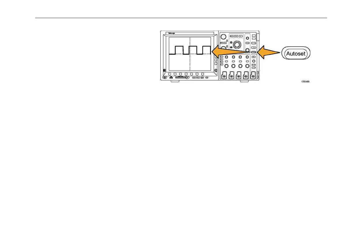
5. Push the Autoset button. The screen
should now display a square wave,
approximately 2.5 V at 1 kHz.
If the signal appears but is misshapen,
perform the procedures for compensating
the probe. (See page 17, Compensating
the Probe.)
If no signal appears, rerun the procedure.
If it no signal still appears, have the
instrument serviced by qualified service
personnel.
Compensating the Probe
Whenever you attach a passive voltage probe for the first time to any input channel, compensate the p robe to match it to
the corresponding oscilloscope input channel.
To properly compensat e your passive probe:
1. Follow the steps for the functional check.
(See page 15, Functional Check.)
DPO4000 Series User Manual 17
 Loading...