Get Acquainted with the Instrument
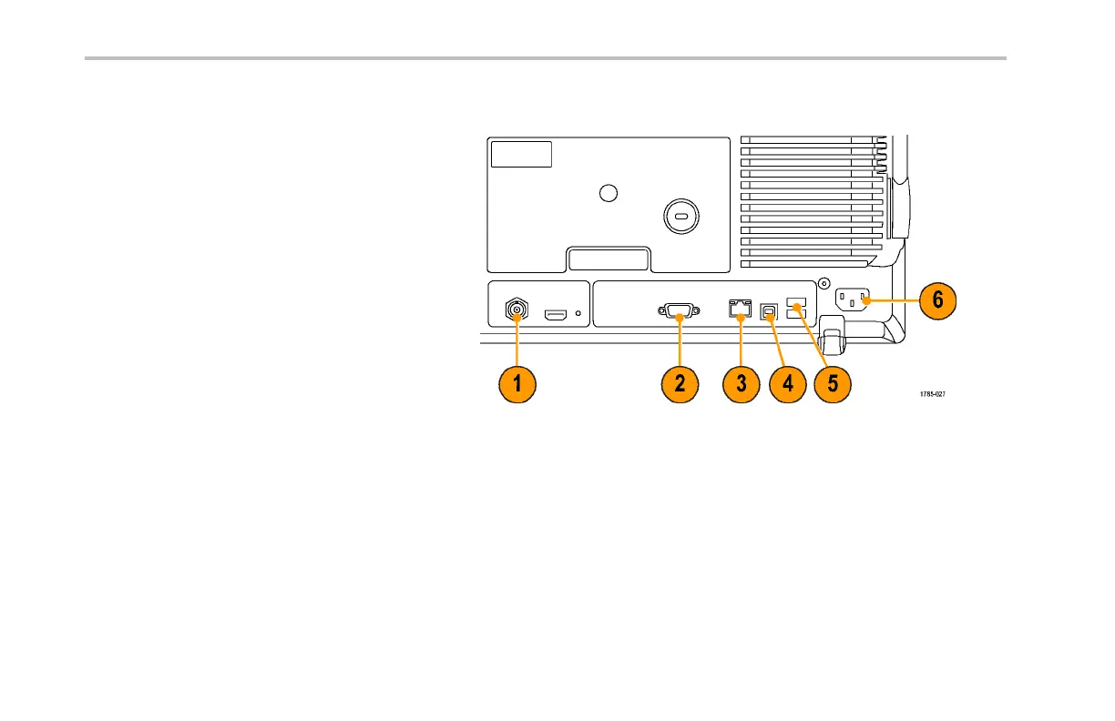
Rear-Panel Connectors
1. Trigger Out. Use the trigger signal output
to synchronize other test equipment
with your oscilloscope. A LOW to HIGH
transition indicates the trigger occurred.
The logic level for Vout (HI) is ≥2.5V open
circuit; ≥1.0 V into a 50Ω load t o ground.
The logic level f or Vout (LO) is ≤0.7 V into
a load of ≤4mA;≤0.25 V into a 50Ω load
to ground.
2. XGA Out.UsetheXGAVideoport(DB-15
female connector) to show the oscilloscope
display on an extern a l monitor or projector.
3. LAN. Use the LAN (Ethernet) port (RJ-45
connector) to connect the oscilloscope to a
10/100 Base-T local area network.
4. Device. Use the U SB 2.0 High speed
device port to control the oscilloscope
through USBTMC or GPIB with a
TEK-USB-488 Adapter. The USBTMC
protocol allows USB devices to
communicate using IEEE488 style
messages. This lets you run your GPIB
software applications on USB hardware.
68 DPO4000 Series User Manual
 Loading...