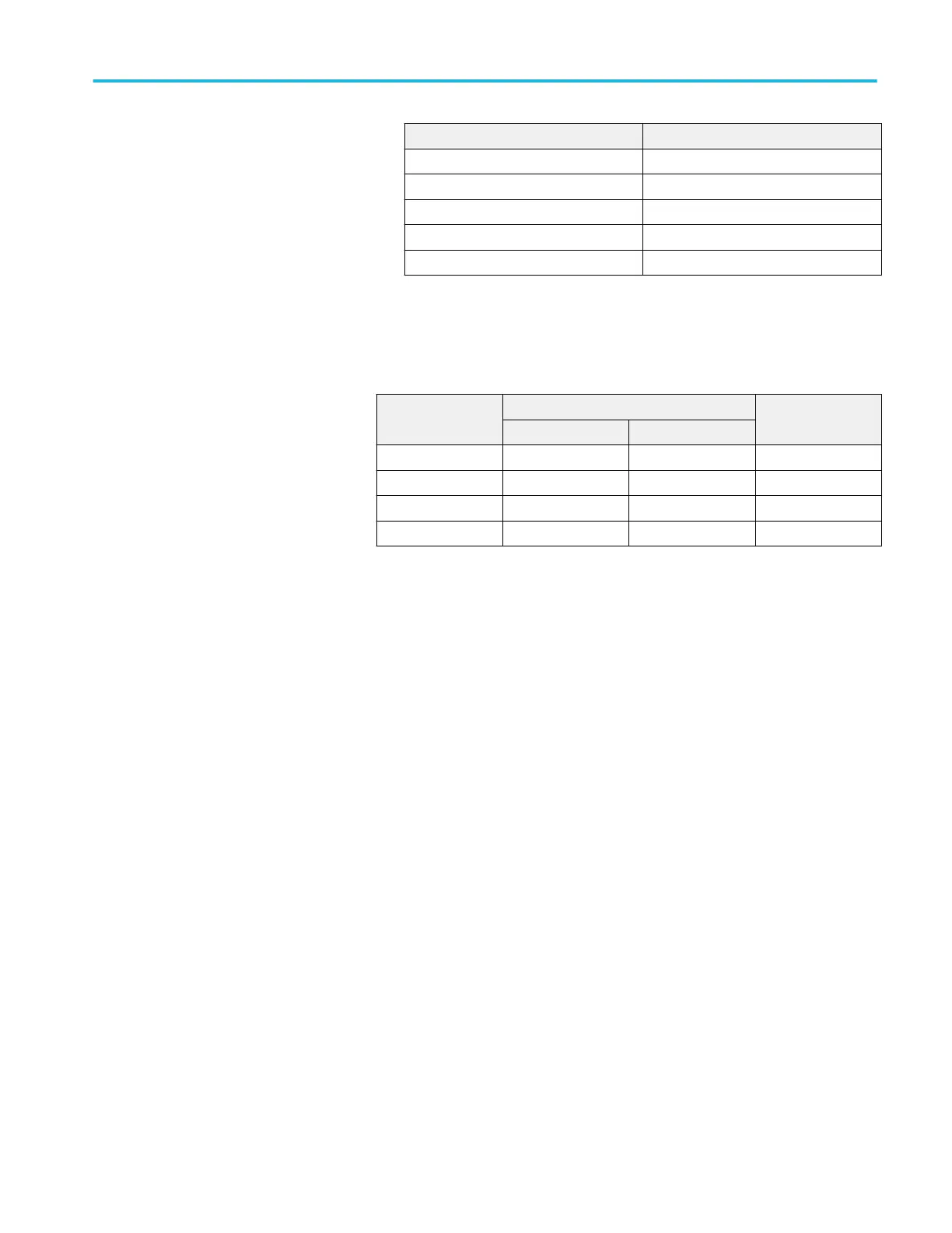
Model Attenuator
≥ 4 GHz models 2X
DPO7354C None
DPO7254C 5X
DPO7104C 5X
DPO7054C 5X
■
Check that a stable trigger is obtained.
c. Repeat step 2, substeps 2.b and 2.c for the full bandwidth selected.
Table 18: Trigger settings for ≥ 4 GHz models
Generator
amplitude
Generator frequency Horizontal scale
A trigger B trigger
10 MHz 10 MHz 200 ns
150 mV 6 GHz 6 GHz 200 ps
200 mV 8 GHz NA 200 ps
500 mV 11 GHz 9 GHz 200 ps
d. ≥ 4 GHz models: Display the test signal:
■
Remove the attenuator.
■
Set the generator frequency to 10 MHz. Set the Horizontal SCALE as
indicated in the table. (See Table 18: Trigger settings for ≥ 4 GHz
models on page 263.)
■
Fine adjust the generator output until the Ch 1 Amplitude readout
indicates the amplitude listed in the table for a frequency not yet
checked. (See Table 18: Trigger settings for ≥ 4 GHz models on
page 263.)
■
Set the generator frequency to the frequency in the table that
corresponds to the amplitude just set. Set the Horizontal SCALE as
indicated in the table. (See Table 18: Trigger settings for ≥ 4 GHz
models on page 263.)
■
CHECK that a stable trigger is obtained.
■
Read the following definition: A stable trigger is one where the
Trig'd LED will remain constantly lighted.
■
Press the Trigger Slope button to select the positive slope.
■
Adjust the Trigger Level knob so that there is a stable trigger.
CHECK that the trigger is stable.
■
Press the Trigger Slope button to select the negative slope. Adjust the
Trigger Level knob so that there is a stable trigger.
■
CHECK that the trigger is stable.
■
Enter pass or fail in the test record.
Performance verification (MSO/DPO70000C, MSO/DPO70000DX, and DPO7000C series)
MSO70000C/DX, DPO70000C/DX, DPO7000C, MSO5000/B, DPO5000/B Series 263
 Loading...


