2601B-PULSE System SourceMeter Instrument Safety Supplement
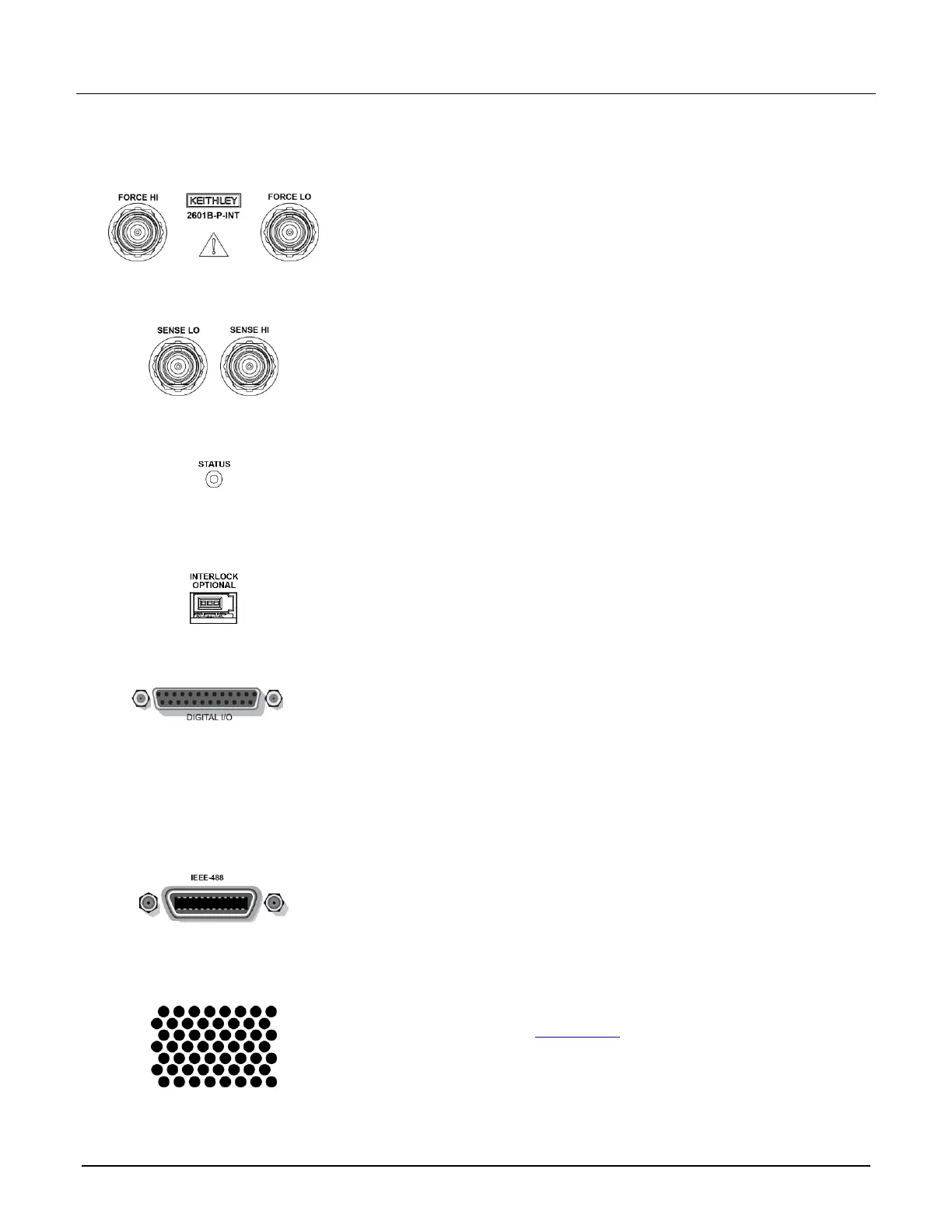
1. FORCE HI and FORCE LO connectors
These connectors provide connections for FORCE HI and FORCE LO.
2. SENSE LO and SENSE HI connectors
These connectors provide connections for SENSE LO and SENSE HI.
This LED indicates the status of the interlock. When the interlock is not
asserted, the indicator is off. When the interlock is asserted, the indicator
is on.
This connector provides a connection for the optional interlock. Refer to
"Using the interlock" in the Model 2601B-PULSE Reference Manual for
information on setting up and connecting the interlock.
Female DB-25 connector. Use a cable equipped with a male DB-25
connector (Keithley Instruments part number CA-126-1).
Pins provided:
▪ Fourteen digital input or output pins
▪ Seven GND pins
▪ Three +5 V pins
Connector for IEEE-488 (GPIB) operation. Use a shielded cable, such as
the Keithley Instruments Model 7007-1 or Model 7007-2.
Exhaust vent for the internal cooling fan. Keep the vent free of obstructions
to prevent overheating. Also see Cooling vents (on page 8).

 Loading...


