Performance Verification
Check DC Gain Accuracy
This test check
s the DC Gain Accuracy of each channel.
1. Push the front-panel Default Setup button to set the instrument to the factory
default setti
ngs.
2. Push the front-panel Horizontal Acquire button, then push the bottom-bezel
Average but
ton, and then push the side-bezel Average button, to turn
averaging on.
NOTE. When using averaging, allow the oscilloscope to acquire all the samples
before taking the measurement.
3. If necessary, use Multipurpose knob a to set the number of averages to 16.
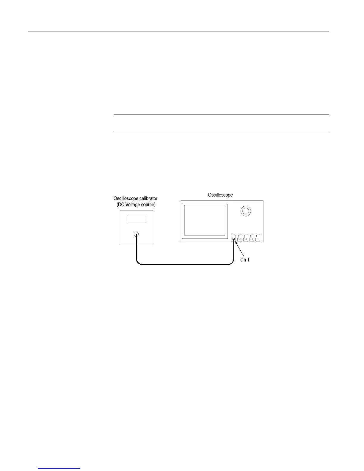
4. Set the DC voltage source to 0 V, and then connect it to channel 1, as shown.
If using a Fluke 9500 as the voltage source, connect the calibrator head to
channel 1.
5. Push the front panel button to select the channel to be tested (1, 2, 3, or 4)
6. Push the bottom-bezel Probe Setup button, and then push the Set to 1X
side-bezel button.
7. PushtheWaveInspectorMeasure button, and then push the bottom-bezel
Add Measurement button.
8. Use Multipurpose knob a to select the Mean measurement, then push the
side-bezel OK Add Measurement button, and then push the Menu Off
button.
9. For each Volts/div line in the following worksheet, perform these steps:
a. Set the channel’s volts/div to the value listed in the worksheet.
b. Set the DC voltage source output level to the positive voltage listed and
record the Mean measurement as V
pos
.
c. Set the DC voltage source to the negative level listed, and record the
Mean measurement as V
neg
.
20 DPO2000 and MSO2000 Series Specifications and Performance Verifi cation
 Loading...