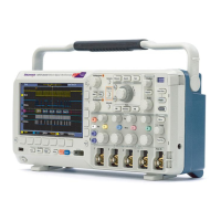
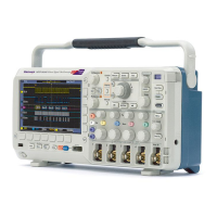
Specifications
This chapter contains specifications for the DPO2000 and the MSO2000 series
oscilloscopes. All specifications are guaranteed unless noted as "typical."
Typical spec
ifications are provided for your convenience but are not guaranteed.
Specifications that are marked with the
symbol are checked in Performance
Verification.
All specifications apply to all DPO2000 and MSO2000 models unless noted
otherwise. To meet specifications, two conditions must first be met:
The oscilloscope must have been operating continuously for twenty minutes
within the operating temperature range specified.
You must perform the Signal Path Compensation (SPC) operation prior to
evaluating specifications. (See page 18, Signal Path Compensation (SPC).)
If the operating temperature changes by more than 10 °C (18 °F), you must
perform the SPC operation again.
Table 1: Analog channel input and vertical specifications
Characteristic Description
DPO2012, MSO2012 DPO20x4, MSO20x4Number of input
channels
2 analog, digitized simultaneously 4 analog, digitized simultaneously
Input coupling
DC, AC, or GND
AC coupling connects a capacitor in se ries with the input circuitry.
GND coupling provides a reference waveform derived from the values identified during SPC. This reference
waveform shows visually where ground is expected to be.
Input resistance, DC
coupled
1MΩ ±2%
Input capacitance, DC
coupled
11.5 pF ±2 pF
Maximum input
voltage
The maximum input voltage at the BNC, between the center conductor and shield is 450 V
peak
(<100 ms
duration), 300 V
RMS
to 4 MHz, derated to 6 V
RMS
at 200 MHz.
D
C Balance
±(1mV+0.1div)
Deskew range ±100 ns, analog channels only
DPO2024, MSO2024 ≥100:1 with 200 MHz sinewave and equal V/div settings on each channel.Crosstalk (channel
isolation), typical
DPO201x, MSO201x ≥100:1 with 100 MHz sinewave and equal V/div settings on each channel.
TekVPI Interface The probe interface allows installing, powering, compensating, and controlling a wide range of probes
offering a variety of features
If a probe requires 12 V bulk power, it must be supplied by the Optional External Power Adapter
The interface is available on all front panel inputs including Aux In
Total probe power
50 W from optional 12 V VPI External Power Adapter
Zero 12 V bulk power without optional External Power Adapter
DPO2000 and MSO2000 Series Specifications and Performance Verification 1