Performance Verification
14. If necessary, t
urn the Horizontal Position knob to set the delay to exactly
1.0000 ms.
15. Compare the ri
sing edge of the marker with the center horizontal graticule
line. The rising edge should cross the 0 V center within ±2.5 divisions
(±25 ns) of the center graticule line. Enter the deviation i n the test record.
NOTE. One division of displacement from graticule center corresponds to a
10 ppm time base error.
Check Digital Threshold
Accuracy (MSO2000 Series
only)
For the MSO2000 se ries only, this test checks the thres hold accuracy of the digital
channels. This procedure applies to digital channels D0 through D15, and to
channel threshold values of 0 V and +4 V.
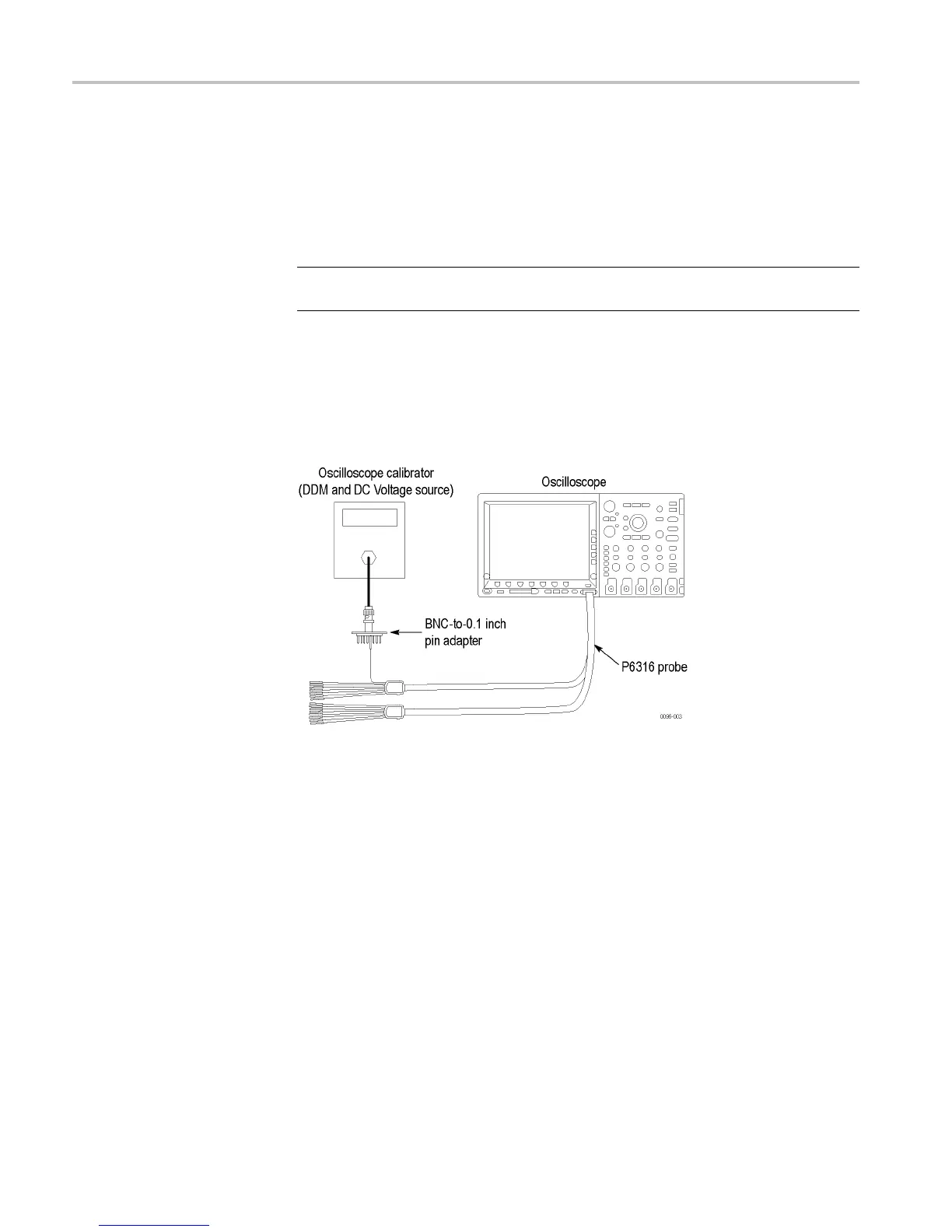
1. Connect the P6316 digital probe to the MSO2000 series instrument.
2. Connect one of the digital channels, such as D0, to the DC voltage source to
run this test.
If using the Fluke calibrator as the DC voltage source, connect the calibrator
head to the digital c hannel to test. You will need a BNC-to-0.1 inch pin
adapter to complete the connection. Be sure to connect the digital channel to
the c orresponding signal pin and to a ground pin on the adapter.
3. Push the front-panel Default Setup button to set the instrument to the factory
default settings.
4. Push the front-panel D15-D0 button.
5. Push the D15-D0 On/Off lower-bezel button.
6. Push the Tu rn On D 7 - D0 and the Turn On D15 - D8 side-bezel buttons.
The instrument will display the 16 digital channels.
7. Push the Thresholds lower-bezel button.
26 DPO2000 and MSO2000 Series Specifications and Performance Verifi cation
 Loading...