Acquire the Sign
al
To acquire data from an I
2
C bus, you need to also set up these items:
1. If you select I
2C, push Define Inputs and
the desired side-bezel menu choices.
B1
I2C
Define
Inputs
Thresholds Include
R/W in
Address
No
B1 Label
I2C
Bus
Display
Event
Table
You can assign the predefi ned SCLK Input
or SD A Input to the channel connected to
the signal.
2. Push Include R/W in Address and then
push the des
ired side-bezel button.
This control determines how the oscilloscope
shows the I
2
C addresses in bus decode
traces, cur
sor readouts, Event Table listings,
and trigger settings.
If you sele
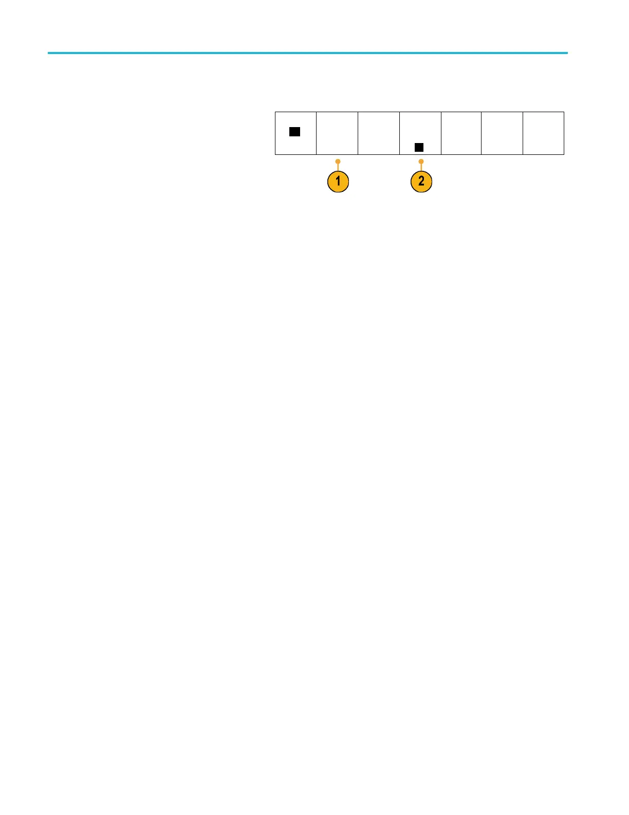
ct Yes, the oscilloscope displays 7-bit addresses as eight bits, where the eighth bit (LSB) is the R/~W bit.
If you sel
ect No, the oscilloscope displays 7-bit addresses as seven bits, and 10-bit addresses as ten bits.
The oscil
loscope also displays 10-bit addresses as 11 bits. The first two bits are the two MSBs of the address. The next
bit is the R/~W bit. The last eight bits are the eight LSBs of the address. (In the physical layer of the I
2
C protocol, 10 bit I
2
C
addresses are preceded by the five bit code, 11110. The oscilloscope never includes these five bits in address readouts.)
54 MSO2000B and DPO2000B Series Oscilloscopes User Manual