EasyManua.ls Logo

Tektronix MSO70404C Printable Help

Tektronix MSO70404C
920 pages
To Next Page IconTo Next Page
To Previous Page IconTo Previous Page
Page #812 background image
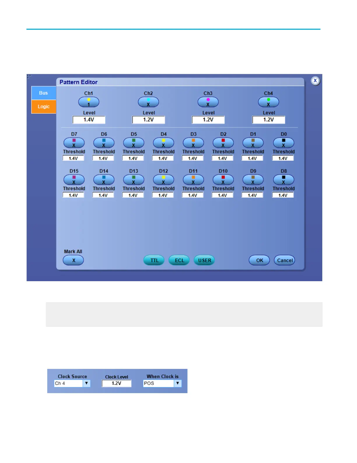
Logic pattern and state pattern editor (digital tab)
Use the controls to set up the Logic Pattern or the Logic State trigger pattern of the channels the instrument uses as logic
waveforms to detect a bus value.
What do you want to do next?
Learn how to define a pattern for the instrument to use to detect a bus value.
Learn about bus setups.
Logic clock inputs
For the supported instruments, you need to connect one of the channel inputs to a clock signal. The instrument combines all of
the channel inputs to form a logic pattern.
Oscilloscope reference
780 DPO70000SX, MSO/DPO70000DX, MSO/DPO70000C, DPO7000C, and MSO/DPO5000B Series

Table of Contents

Other manuals for Tektronix MSO70404C

Question and Answer IconNeed help?

Do you have a question about the Tektronix MSO70404C and is the answer not in the manual?

Tektronix MSO70404C Specifications

General IconGeneral
Bandwidth4 GHz
Channels4
Sample Rate (Digital)10 GS/s
Operating SystemWindows
Probe InterfaceTekVPI
Display12.1 in. color TFT LCD
Vertical Resolution8 bits
Input Impedance50 Ω or 1 MΩ
Maximum Input Voltage (50 Ω)5 Vrms
Maximum Input Voltage (1 MΩ)400 V peak
Trigger TypesEdge, Pulse, Runt, Timeout, Window, Logic, Video

Related product manuals