RSA306 USB Real-Time Spectrum Analyzer Demo Guide
7
Demo 3: EMI spurious
The spurious measurement in the RSA306 is set up to
change limits vs. frequency, and antenna correction factors
have been applied, resulting in the sloped noise floor of the
displayed signal. Violations above the user-set limits are
shown in red on the table. This example shows how to use
the spurious display in RSA306 to perform EMI pre-
compliance and diagnostics.
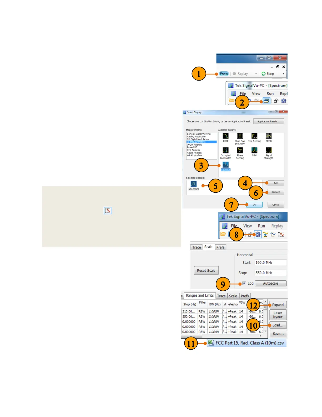
1. Click Presets.
2. Click the Display button.
3. Under the RF Measurement, select Spurious
from the Available displays box.
4. Click Add to add the application to the Selected
Displays list.
5. Select the Spectrum icon in the Selected Displays
list.
6. Click Remove to clear the icon from the list.
7. Click OK.
8. Click the settings button.
9. In the Scale tab, select the Log scale to reset the
display to show the frequency axis in a logarithmic
scale.
10. Under the Ranges and Limits tab, click Load to
select the appropriate limit line and measurement
condition.
11. Please select FCC Part 15, Rad, Class A
(10m).csv from the C:/SignalVu-PC
Files/Examples directory for this exercise.
12. A larger new resized window of range and limit
table can be displayed by clicking Expand.
Quick Tips: Loss correction
The External Gain/Loss Correction tab under the
amplitude control panel ( ) allows you to apply a
correction to a signal to compensate for the use of
external equipment, such as an amplifier or attenuator.
External Loss Table can be used to apply a frequency
dependent gain/loss correction to the signal.