EasyManuals Logo
Home>Tektronix>Measuring Instruments>RSA306B

Tektronix RSA306B Installation And Safety Instructions

Tektronix RSA306B
26 pages
To Next Page IconTo Next Page
To Previous Page IconTo Previous Page
Page #21 background imageLoading...
Page #21 background image
Installation
Front-panel connections
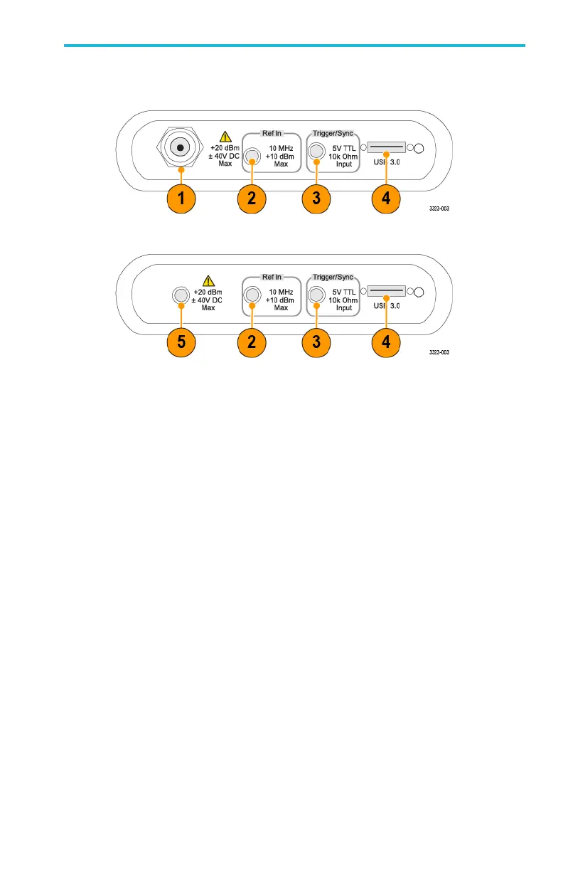
Figure 3: RSA306B front panel
Figure 4: RSA306B-SMA front panel
1– N-type RF input connector
This N-type female connector receives the RF signal input, via cable or
antenna. The input signal frequency range is 9 kHz to 6.2 GHz.
2– Ref In (external reference) connector
Use this SMA female connector to connect an external 10 MHz
reference clock signal to the analyzer.
3– Trigger/Sync connector
This SMA female connector accepts TTL-level signals (0 5.0 V), and
can be rising- or falling-edge triggered.
RSA306B an d RSA306B-SMA Installation and Safety Instructions 11

Other manuals for Tektronix RSA306B

Questions and Answers:

Question and Answer IconNeed help?

Do you have a question about the Tektronix RSA306B and is the answer not in the manual?

Tektronix RSA306B Specifications

General IconGeneral
BrandTektronix
ModelRSA306B
CategoryMeasuring Instruments
LanguageEnglish

Related product manuals