Appendix B: Performance Veritication
-,I_
19. Disconnect the test hook up from the CH 2 input
connector.
Time Base System Checks
This procedure chec!~ those characteristics that. relate to the Main and Delayed
time
base system and are listed as checked
under Warrankd Chamctoirtics
in
the Spcci$cations section.
Check Long-Term Sample
Rate and Delay Time
Accuracy
Equipment Required: One time-marker generator (Item 9), one precision
coaxial cable, (Item 2) and one 50 Q termination (Item 1).
Time Required: Approximntcly 5 minutes.
Prerequisites: See page B-5.
Procedure:
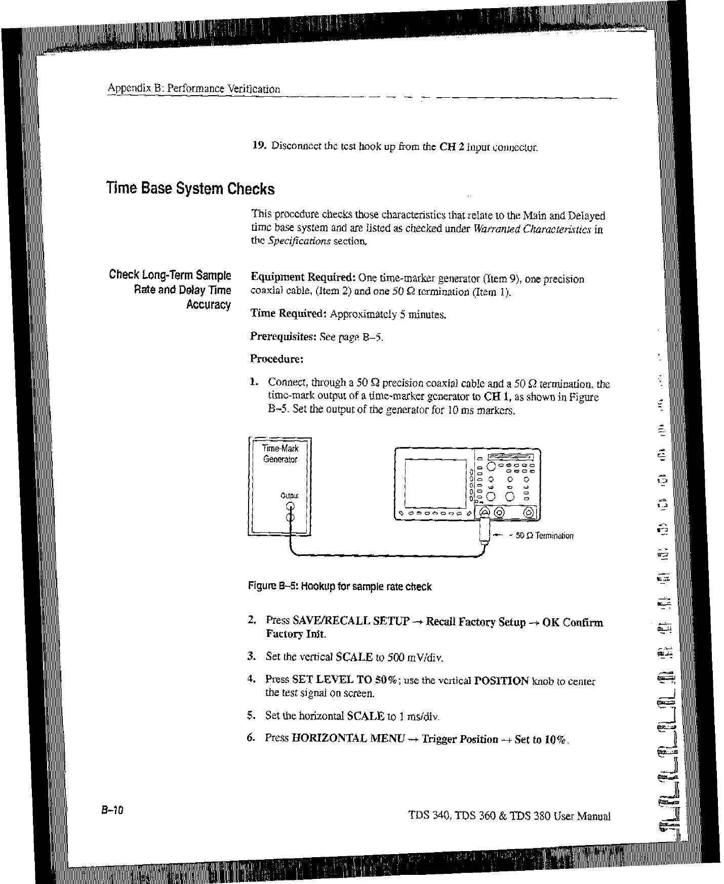
1. Connect, through a 50 Q precision coaxial cable and a 50 Q termination, the
time-mtuk output of a time-marker generator to CH 1, as shown in Fibwe
B-5. Set the output of the generator for 10 ms markers.
bl
- SO II Termioafion
Figure B-5: Hookup for sample rate check
2. Press SAVE/RECALL SETUP -+
Recall
Factory Setup -+ OK Confirm
Factory Init.
3.
Set the vertical SCALE to 500 mV/div.
4.
Press SET LEVEL TO ,SO%: use the vcrticti POSITION knob to center
the test signal on
screen.
5. Set the horizontal SCALE to 1 ms/div.
6.
PXSS HORIZONTAL MENU-t
Trigger
Position -t Set to 10%.
TDS 340, TDS 360 & TDS 380 User Manual
Artisan Technology Group - Quality Instrumentation ... Guaranteed | (888) 88-SOURCE | www.artisantg.com
 Loading...


