Cursor Measurements
TDS 620A, 640A, & 644A User Manual
3Ć19
In FastFrame mode, the @ shows the time position of the selected cursor
relative to the trigger point of the frame that the selected cursor is in. The
D
shows the time difference between the two cursors only if both cursors
are in the same frame.
H
Paired: the value after one
D
shows the voltage difference between the
the two
X
s; the other
D
shows the time (or frequency) difference between
the two long vertical bars. The value after @ shows the voltage at the
X
of the selected cursor relative to ground (see Figure 3-11).
In FastFrame mode, the
D
shows the time difference between the two
cursors only if both cursors are in the same frame.
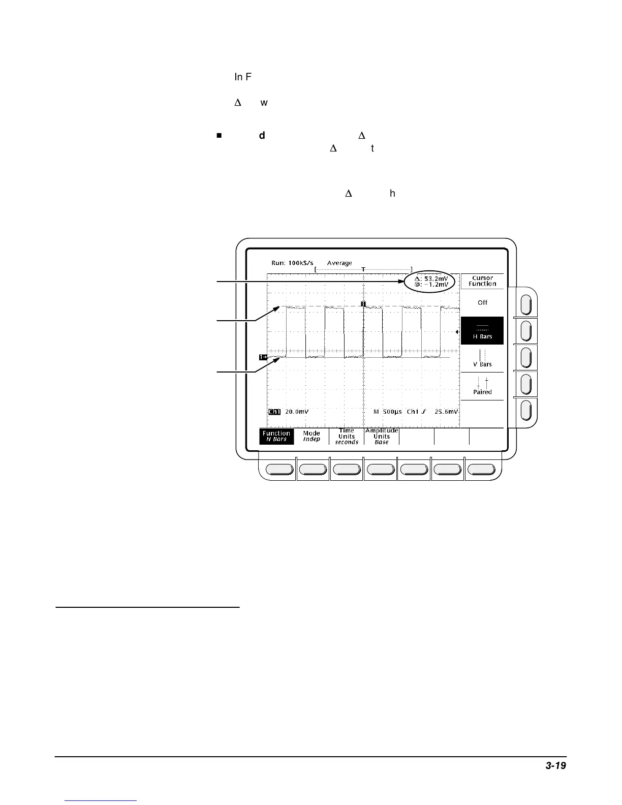
Non-selected Cursor
(Dashed Line)
Selected Cursor
(Solid Line)
Cursor Readout (H Bars)
Figure 3-10: H Bars Cursor Menu and Readouts
Paired cursors can only show voltage differences when they remain on
screen. If the paired cursors are moved off screen horizontally, Edge will
replace the voltage values in the cursor readout.
To take cursor measurements, press CURSOR to display the Cursor menu
(Figure 3-10).
Function
Select the type of cursors you want using the Function menu item:
Press CURSOR ➞ Function (main) ➞ H Bars, V Bars, Paired, or Off (side).
Operation

 Loading...