Performance Verification
1. Set up the oscil
loscope as shown in the following table:
Push menu button Select menu option Select setting
Default Setup
——
Channels 1, 2, 3, 4
Probe 1X
Channels 1, 2, 3, 4 Volts/Div 5 0 mV/div
Source
Ext
1
Trig Menu
Mode Auto
Acquire
Sample
—
Source Channel under test
Measure
Type Mean
1
The test operates without a trigger. To maintain uniformity and to avoid false triggering on noise, the Ext trigger is
the recommended source.
2. Make a spreadsheet approximately as shown in the example in Appendix
A. You only need to enter the values for column A and the equations. The
values in columns B, C, D, E, F, and G are example s of the measured o
r
calculated values.
The PDF version of the TDS2000C service manual (which you can download
from the www.tektronix.com Web site), includes an empty spreadsheet for
your convenience. To access and save the test spreadsheet, see the instructions
in Appendix A: Example of a Vertical Position Accuracy Test Spreadsheet
on page A-1.
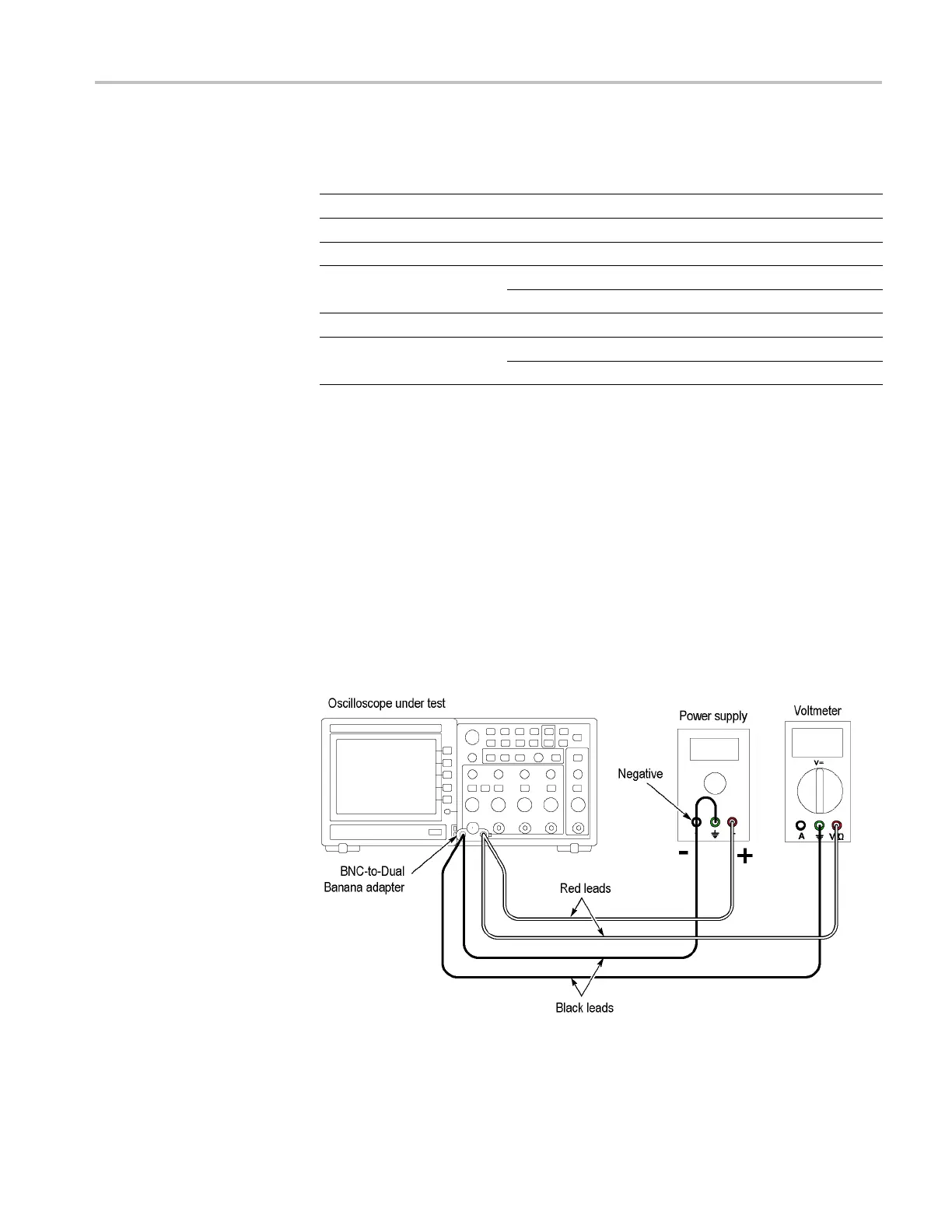
3. Connect the oscilloscope, power supply, and voltmeter as shown in the
following figure:
4. Set the power supply to the 1.8 V value shown in column A, the Approximate
Test Voltage.
TDS2000C Series Oscilloscope Service Manual 4–11

 Loading...
