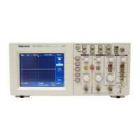
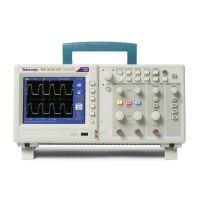
Do you have a question about the Tektronix TDS2024B and is the answer not in the manual?
Safety precautions for avoiding fire and personal injury during product use.
Details technical specifications for the TDS1000B and TDS2000B oscilloscopes.
Lists general physical and environmental specifications of the oscilloscopes.
Lists necessary equipment for performance verification procedures.
Outlines the steps for verifying the oscilloscope's performance against specifications.
Details the procedure to verify the DC gain accuracy of all input channels.
Describes the test to verify the analog bandwidth of all input channels.
Outlines the procedure to check time base accuracy and sample rate.
Details the test for verifying edge trigger sensitivity on all input channels.
Explains the procedure to test the edge trigger sensitivity for the external trigger input.
Describes how to verify the vertical position accuracy and DC measurement accuracy.
Lists the equipment needed to perform the adjustment procedures.
Provides the detailed steps for loading new calibration constants.
Precautions to prevent electrostatic discharge damage to components.
Procedures for removing and installing various modules within the oscilloscope.
Detailed steps for removing and installing the power supply module.
Detailed steps for removing and installing the main board module.
Steps for removing and installing the display module for color and monochrome units.
Information and procedures for isolating defective modules in the oscilloscope.
Guides users through troubleshooting steps using flowcharts.
Steps to diagnose and resolve power supply issues.
Steps to diagnose and resolve issues with a nonfunctional display.
Steps to troubleshoot an improperly functioning front panel.
Steps to troubleshoot issues with the main board (acquisition module).
| Bandwidth | 200 MHz |
|---|---|
| Channels | 4 |
| Sample Rate | 2 GS/s |
| Vertical Resolution | 8 bits |
| Timebase Range | 5 ns/div to 50 s/div |
| Trigger Modes | Auto, Normal, Single |
| Display Resolution | 320 x 240 pixels |
| Dimensions | 149 mm (5.9 in) Height x 326 mm (12.8 in) Width x 124 mm (4.9 in) Depth |
| Input Coupling | AC, DC, GND |
| Vertical Sensitivity | 2 mV to 5 V/div |
| Trigger Types | Edge, Pulse, Video |
| Display Type | Color LCD |
| Display Size | 5.7 inches |
| Interfaces | USB |
| USB Interface | USB 2.0 |
| Input Impedance | 1 MΩ ± 2% |
| Timebase Accuracy | 50 ppm |
| Power Supply | 100 to 240 V ±10% at 50 to 60 Hz |


 Loading...