PS280 and PS283 Adjustment Procedures
18
Handheld and Benchtop Instruments Basic Service
To adjust the SLAVE voltage output, perform the following steps.
1. Disengage both TRACKING mode switches (both switches out) so that the
power supply is in the INDEPendent operating mode.
2. Set the SLAVE AMPS/VOLTS meter selection switch to VOLTS.
3. Set the digital multimeter to measure a DC voltage of
±16 mV.
4. Set the power supply SLAVE VOLTAGE control to minimum (fully
counterclockwise).
5. Connect the digital multimeter to the + and – terminals of the SLAVE
output.
6. Adjust VR302 (Master/Slave circuit board) for a reading of –15 mV, within
±15 mV on the multimeter.
7. Set the digital multimeter to measure a DC voltage of
±35 V.
8. Set the SLAVE VOLTAGE control to maximum (fully clockwise).
9. Adjust VR301 (Master/Slave circuit board) for a reading of 31.5 V on the
multimeter.
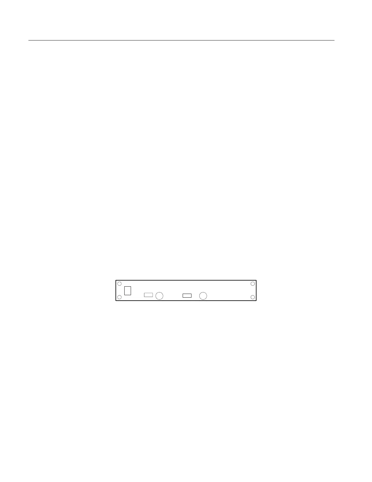
10. Adjust VR601 (Display Assembly circuit board) until the PS280/PS283
front panel display reads 31.5 V.
11. Disconnect the digital multimeter from the power supply.
VR601
VR602
VR201
VR202
J1044
Figure 8: Display Assembly Circuit Board Adjustments
To adjust the MASTER current output, perform the following steps.
1. Disengage both TRACKING mode switches (both switches out) so the
power supply is in the INDEPendent operating mode.
2. Set the MASTER AMPS/VOLTS meter selection switch to AMPS.
3. Set the digital multimeter to measure a DC current of 2 A.
4. Connect the digital multimeter to the + and – terminals of the MASTER
output.
5. Set the MASTER CURRENT control to maximum (fully clockwise).
SLAVE Voltage Output
MASTER Current Output
 Loading...


