TAS 200 Series Adjustment Procedures
42
Handheld and Benchtop Instruments Basic Service
Cursors and Readout Adjustments
To locate the adjustments for the following procedures, refer to Figure 13. The
Control and I/O board occupies the top left-hand corner of the instrument.
Use the following procedure to adjust the cursor accuracy.
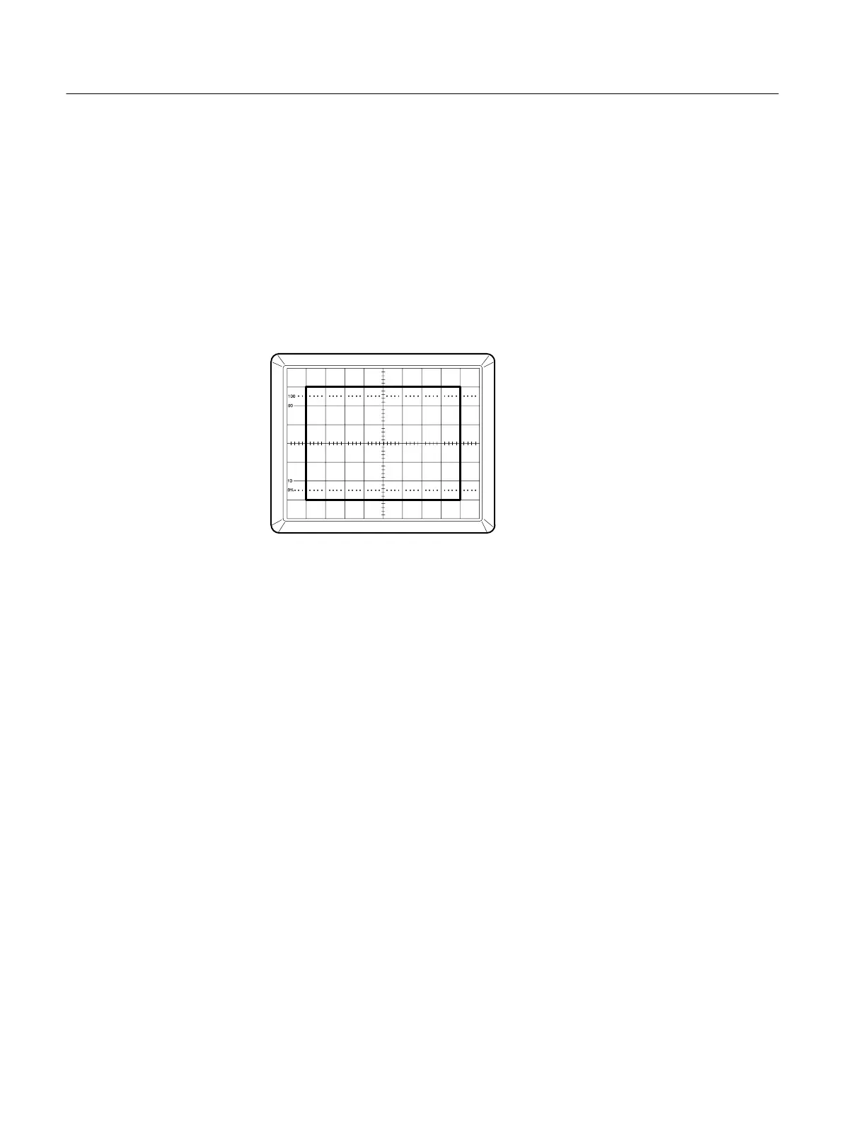
1. Simultaneously press the front panel PROBE X1/X10 and the ∆V/∆T 1/∆T
push switches to display the cursor calibration square.
Figure 12: Cursor Calibration Display
2. On the Control and I/O board, adjust the following potentiometers to
position the alignment square as shown in Figure 12. See Figure 13 for the
adjustment locations.
X-Gain: VRA01
X-Position: VRA02
Y-Gain: VRA03
Y-Position: VRA04
3. Simultaneously press the PROBE X1/X10 and the ∆V/∆T 1/∆T push
switches again to exit the adjustment mode.
Cursor Accuracy
 Loading...


