TAS 200 Series Adjustment Procedures
Handheld and Benchtop Instruments Basic Service
27
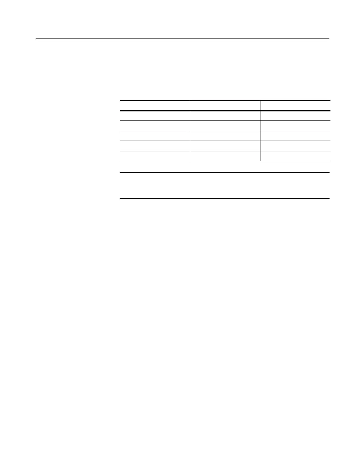
4. Verify that the voltage levels in Table 21 are within the specified limits. See
Figure 7 for the test point locations.
Table 21: Power Supply Limits
Power Supply Test Point Limits (Volts)
+12 +12 +11.95 to +12.05
–12 –12 –11.80 to –12.20
+5 +5 +4.75 to +5.25
+185 (TAS 220) +185 +180 to +190
+145 (TAS 250) +145 +140 to +150
NOTE. If a power supply measurement exceeds the limits specified in Table 21,
discontinue the adjustment procedures. Contact a Tektronix service center for
instrument repair.
5. Disconnect the voltmeter from the instrument.
Use the following procedure to adjust the display intensity.
1. Set up the oscilloscope as follows:
HORIZONTAL SEC/DIV 1 ms
TRIGGER HOLDOFF NORM
2. Rotate the front panel INTENSITY control to the fully counterclockwise
position; then rotate the control clockwise to the 90_ (nine o’clock) position.
3. Locate VR603 on the Power and High Voltage board (see Figure 7 for the
adjustment location). Adjust VR603 until the trace is barely visible.
4. Rotate the INTENSITY control clockwise. Verify that the trace becomes
brighter. Rotate the INTENSITY control fully counterclockwise; the trace
should disappear.
Use the following procedure to adjust the display focus and astigmatism.
1. Set the front panel FOCUS control to midrange; then adjust VR602 on the
Power and High Voltage board to obtain the best focus. See Figure 7 for the
adjustment location.
2. Set the front panel HORIZONTAL X-Y push switch to the in position.
Intensity
Focus and Astigmatism
 Loading...


