TAS 200 Series Adjustment Procedures
34
Handheld and Benchtop Instruments Basic Service
Use the following procedure to adjust the vertical input attenuator compensation.
1. Set up the oscilloscope as follows:
VERTICAL MODE BOTH
CH 1 (CH 2) VOLTS/DIV 0.1 V
CH 1 (CH 2) VARIABLE CAL
CH 1 (CH 2) AC-DC DC
2. Connect a 1 kHz square wave to the CH 1 (CH 2) input. Adjust the generator
output to produce a waveform five divisions in amplitude on the display.
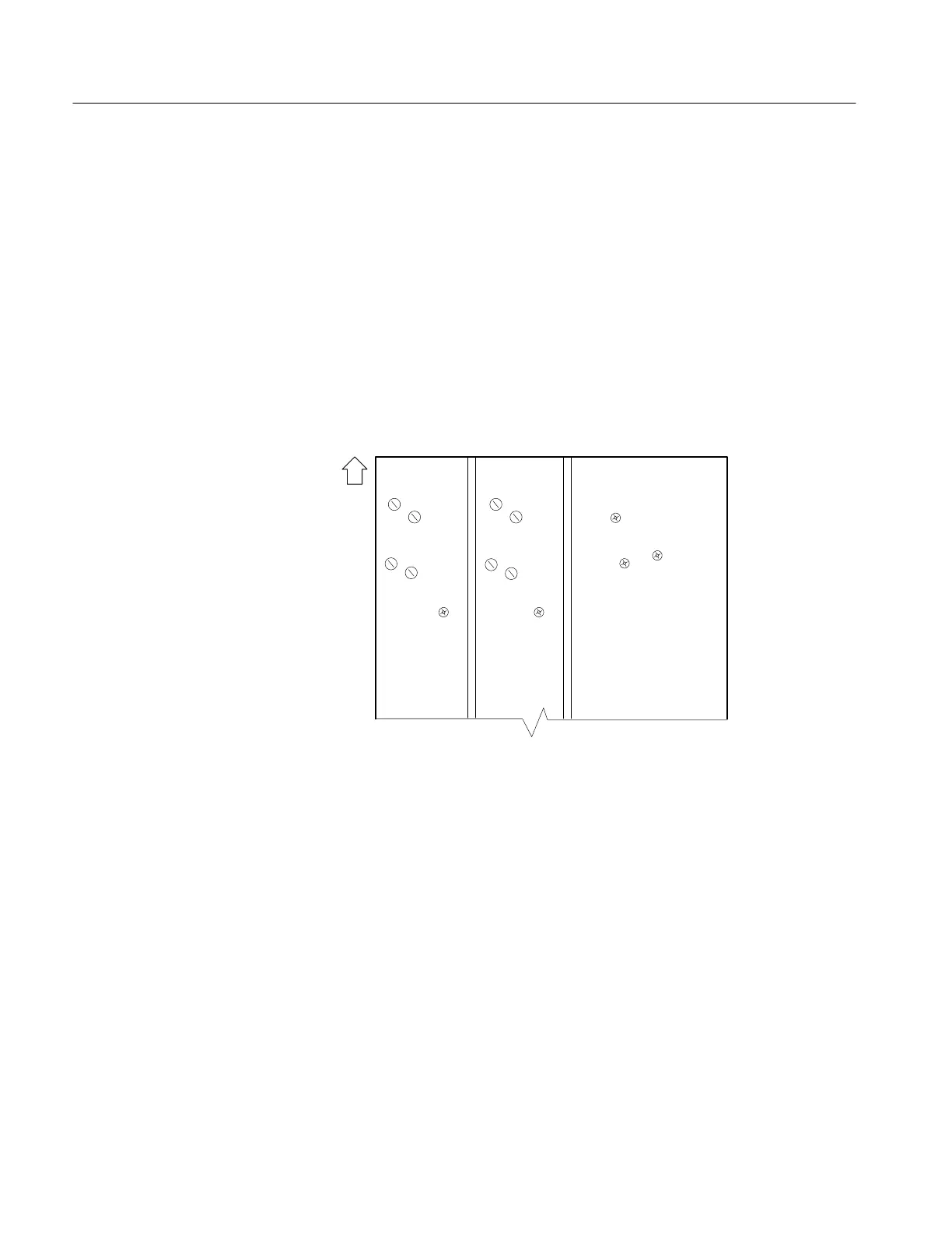
3. Adjust VC102 (VC202) to obtain an optimum waveform symmetry with
minimal overshoot. See Figure 10 for the adjustment locations.
Instrument
front
VC101
VC103
VC102
VC104
VC203
VC201
VC202
VC204
1/10
1/100
1/10
1/100
STEP BAT
VR101
X-AXIS DC
OFFSET
VR401
TRIG BAL
VR403
TRIG CENT
VR407
STEP BAT
VR201
Figure 10: Main Board (Viewed from the Instrument Bottom)
4. Set the CH 1 (CH 2) VOLTS/DIV control to 1 V.
5. Readjust the generator output to produce a waveform five divisions in
amplitude. Adjust VC104 (VC204) to obtain an optimum waveform
symmetry with minimal overshoot. See Figure 10 for the adjustment
locations.
6. Disconnect the square wave generator from the instrument.
7. Connect a 10X probe to the CH1 (CH 2) input
8. Set the CH 1 (CH 2) VOLTS/DIV control to 10 mV/division.
Attenuator Compensation
 Loading...


