Removal and Installation Procedures
TLA5000 Series Service Manual
6-23
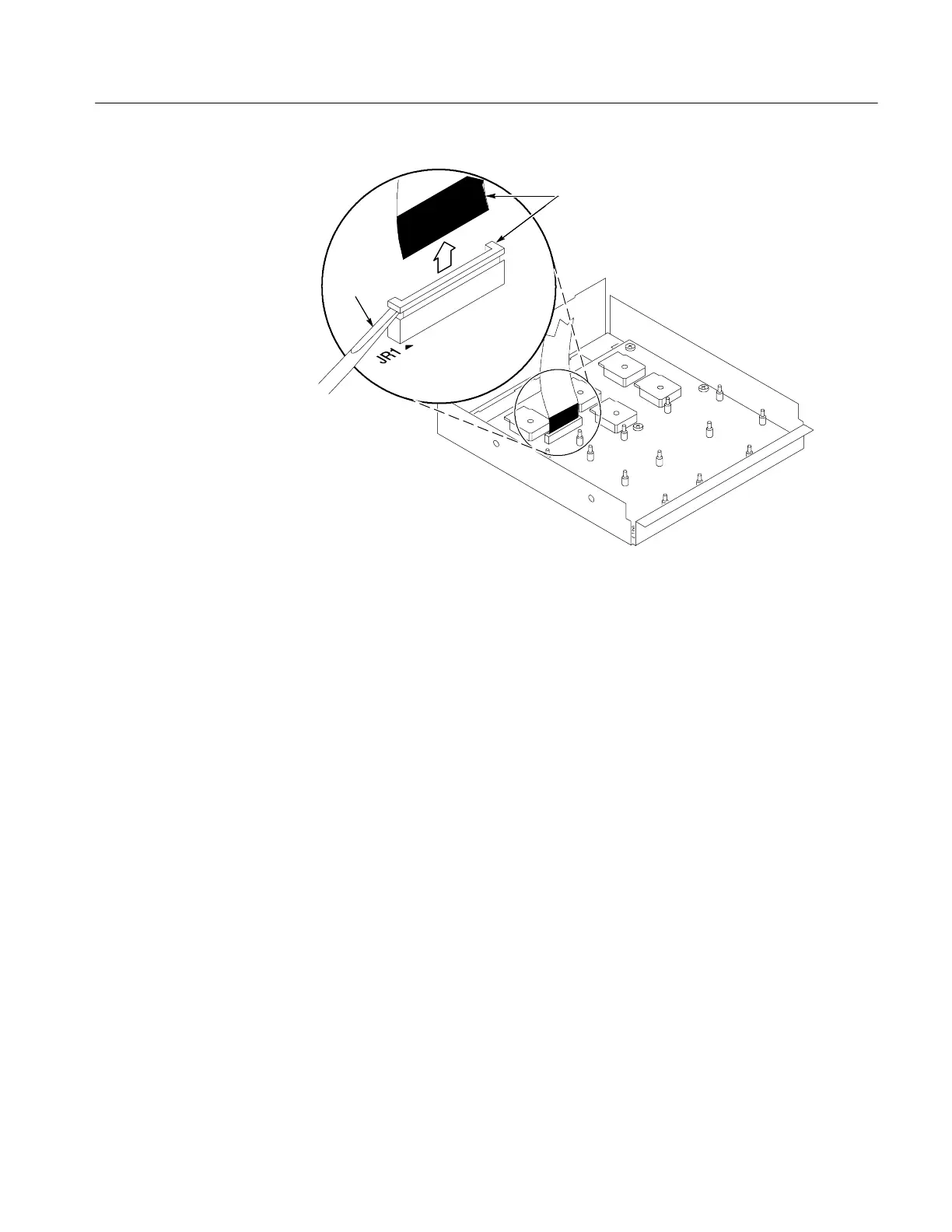
Black stripe
toward connector
Screwdriver
Figure 6- 11: JR1 flex cable connector removal
Front Panel Board
1. Remove the trim and covers by following the procedure on page 6--6.
2. Remove the front panel knobs.
3. Remove the front panel assembly.
4. Remove the eight T-15 Torx-drive screws that secure the Front panel board
to the Front panel assembly. See Figure 6--12, page 6--24.
5. Pry the board up off the alignment s tuds. Place a Use flat bladed screwdriver
in the pry point access holes to pry the board up from the assembly.
6. To reinstall the front panel board do steps 1 through 5 in reverse order.
Tighten the T-15 Torx-drive screws to 8-in lbs.