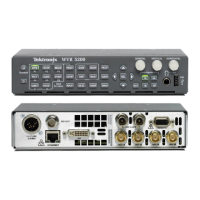
Incoming Inspection
Analog Audio Output
(Option AD & DDE)
1. Press the FACTO
RY button to restore the factory preset.
2. Press and hold the DISPLAY SELECT 4 button to display the AUDIO
pop-up menu.
3. Select Audio Input > Analog A.
4. Press the AUDIO button to close the menu.
5. Using the audio breakout cable or equivalent, connect the first Line A input
pair to the analog audio generator and verify that the output level of the
generator is indicated on the audio bars w ith an 18 dBu signal.
6. Press the CONFIG button to display the CONFIG menu.
7. In the Audio Inputs/Outputs submenu, set Attenuate A udio Output to
0 dB (press SEL and use the GENERAL knob to adjust the value, then press
SEL again when you have set the value).
8. While in the Audio Inputs/Outputs submenu, select Analog A > Analog
Output Map.
9. Press the SEL button to display the Analog Output to Analog "A" Bar Map.
10. Put an X in the first bar pair position for Analog Outputs 1&2, 3&4, 5 &6,
and 7&8.
11. Press the CONFIG bu tton to exit the CONFIG menu.
12. Connect the first analog output pair on the breakout cable to the second line
A input pair.
13. Verify on the level meter bars that the second set of bars is within 1 dB of the
first set of bars.
14. Connect the second analog output pair on the breakout cable to the second
line A input pair.
15. Verify on the level meter bars, that the second set of bars is within 1 dB of the
first set of bars.
16. Connect the third analog output pair on the breakout cable to the second line
A input pair.
17. Verify on the level meter bars, that the second set of bars is within 1 dB of the
first set of bars.
18. Connect the fourth analog output pair on the breakout cable to the second
line A input pair.
19. Verify, on the level-meter bars, that the second set of bars is within 1 dB o f
the first set of bars.
20. Record Pass or Fail in the test record.
62 Waveform Rasterizers Specifications and Performance Verification
 Loading...


