5
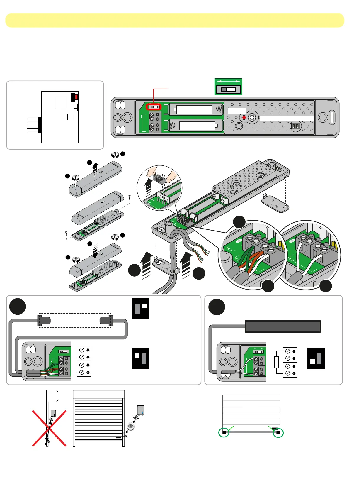
2.2 Mounting the wireless safety system (BST24/BST25/BST25S)
We recommend installing at the base of the door, on both
side of the safety edge, two rigid bumpers. In case of
uneven floors, this can avoid an accidental activation of the
safety edge. If it’s not possible use the procedure 3.3.
The system is composed by a radio card (MASTER), plugged in the control unit, and a wireless transmitter
(SLAVE) mounted on the door, usually close to the bottom slat, connected to the safety device.
The device has got infrared low-consumption barrier (both safety systems), or 8,2KOhm resistive barrier safety
edge (only for BST24/BST25). If an obstacle is detected during the closing, the SLAVE sends a signal to the
MASTER that immediately stops the door and reverses its movement. The system performs an auto-test before
any movement.
OK
RIGID BUMPERS
FLOOR
RADIO CARD (MASTER)
Install both the control unit and bottom slat transmitter
inside. Make sure that there are no obstructions
between devices. Check that the maximum distance
between the devices is no more than 10m.
1
BK2
2 3 4 5 6
BK2
1
2
1
BK2
2 3 4 5
6
BK2
2
1
1
BK2
2 3 4 5 6
BK2
1
BK2
2 3 4 5 6
BK2
Green
Brown
White
1
BK2
2 3 4 5 6
BK2
Green
Brown
White
1
BK2
2 3 4 5 6
BK2
Green
Brown
White
2
a b
+
B1
-
B2
3 4 5 6
BK2
1 2
+ -
- +
+ -
- +
+
B1
-
B2
3 4 5 6
BK2
1 2
a
b
+
B1
-
B2
3 4 5 6
BK2
1 2
+ -
- +
BOTTOM SLAT TRANSMITTER (SLAVE)
Powered by:
led *
dip switches **
+
B1
-
B2
34 56
BK2
12
+-
-+
+-
-+
+
B1
-
B2
34 56
BK2
12
2 x 3.6V
Lithium batteries
2 x 1.5V
Type AA batteries
1
BK2
2 3 4 5 6
BK2
Green
Brown
White
1
BK2
2 3 4 5 6
BK2
Green
Brown
White
1
3
1
BK2
2 3 4 5 6
BK2
Green
Brown
White
2
a b
+
B1
-
B2
3 4 5 6
BK2
1 2
+ -
- +
+ -
- +
+
B1
-
B2
3 4 5 6
BK2
1 2
a
b
+
B1
-
B2
3 4 5 6
BK2
1 2
+ -
- +
1
BK2
2 3 4 5 6
BK2
Green
Brown
White
1
BK2
2 3 4 5 6
BK2
Green
Brown
White
1
BK2
2 3 4 5 6
BK2
Green
Brown
White
2
a b
+
B1
-
B2
3 4 5 6
BK2
1 2
+ -
- +
+ -
- +
+
B1
-
B2
3 4 5 6
BK2
1 2
a
b
+
B1
-
B2
3 4 5 6
BK2
1 2
+ -
- +
Opening the lid
1. Remove the screws.
2. Lift the lid up.
Closing the lid
1. Place the lid.
2. Tighten the screws.
Fixing the
transmitter
Use the screws and
the holes in the picture.
Insert batteries and
check polarity.
INFRARED SAFETY EDGE RESISTIVE SAFETY EDGE
1 2
ON
DIP1 = ON
1 2
ON
DIP2 = ON
1
BK2
2 3 4 5 6
BK2
Green
Brown
White
1
BK2
2 3 4 5 6
BK2
Green
Brown
White
1
BK2
2 3 4 5 6
BK2
Green
Brown
White
+
B1
-
B2
3 4 5 6
BK2
+ -
- +
+ -
- +
+
B1
-
B2
3 4 5 6
BK2
1 2
a
b
+
B1
-
B2
3 4 5 6
BK2
1 2
+ -
- +
1
BK2
2 3 4 5 6
BK2
Green
Brown
White
1
BK2
2 3 4 5 6
BK2
Green
Brown
White
1
BK2
2 3 4 5 6
BK2
Green
Brown
White
2
a b
+
B1
-
B2
3 4 5 6
BK2
1 2
+ -
- +
+ -
- +
+
B1
-
B2
3 4 5 6
BK2
1 2
a
b
+
B1
-
B2
3 4 5 6
BK2
1 2
+ -
- +
1
ON
B2B1
2
++
P1
6 5 4 3
8K2
6 5 4 3
4- GREEN
5- BROWN
6- WHITE
3 4 5 6
BK2
Green
Brown
White
3 4 5 6
BK2
Green
Brown
White
1
BK2
2 3 4 5 6
BK2
Green
Brown
White
1
BK2
2 3 4 5 6
BK2
Green
Brown
White
1
BK2
2 3 4 5 6
BK2
Green
Brown
White
2
a b
+
B1
-
B2
3 4 5 6
BK2
1 2
+ -
- +
+ -
- +
+
B1
-
B2
3 4 5 6
BK2
1 2
a
b
+
B1
-
B2
3 4 5 6
BK2
1 2
+ -
- +
1
BK2
2 3 4 5 6
BK2
Green
Brown
White
1
BK2
2 3 4 5 6
BK2
Green
Brown
White
1
BK2
2 3 4 5 6
BK2
Green
Brown
White
2
a b
+
B1
-
B2
3 4 5 6
BK2
1 2
+ -
- +
+ -
- +
+
B1
-
B2
3 4 5 6
BK2
1 2
a
b
+
B1
-
B2
3 4 5 6
BK2
1 2
+ -
- +
1
ON
B2B1
2
++
P1
6 5 4 3
8K2
6 5 4 3
4- GREEN
5- BROWN
6- WHITE
3 4 5 6
BK2
Green
Brown
White
3 4 5 6
BK2
Green
Brown
White
1 2
ON
DIP1 = OFF
Infrared test activated for
30 s. Any beam interruption
turns the led ON .
*
*
*
(*) Only for BST24 / BST25
 Loading...