This document provides a setup guide for the Teleco Simple Panel, specifically for a wired safety edge system, manufactured by Rollerdoor UK. It covers installation, wiring, programming, and troubleshooting for a garage door control panel.
Function Description
The Teleco Simple Panel is a control unit designed for operating garage doors, particularly those with a wired safety edge system. It manages motor functions, safety features, and remote control programming, ensuring safe and reliable operation of the door. The panel includes features for setting motor limits, programming transmitters for single or dual-channel operation, and managing safety edge exclusions.
Important Technical Specifications
- Motor Wiring:
- Left Hand Motor: Black wire to terminal 5, Blue wire to terminal 6, Brown wire to terminal 7.
- Right Hand Motor: Brown wire to terminal 5, Blue wire to terminal 6, Black wire to terminal 7.
- Wired Safety Edge Wiring:
- Brown wire to terminal 16.
- Green wire to terminal 17.
- White wire to terminal 18.
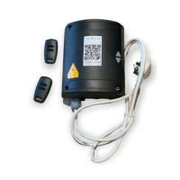
- The spiral cables are pre-wired into a junction box; only the opposite end needs to be wired into the control panel.
- A green LED light inside the junction box indicates correct wiring and no faults.
- Motor Limit Adjustment:
- Adjusted via screws on the motor.
- Arrows on the motor indicate the direction of rotation for the tube motor.
- Right Hand Motor: RED = Down limit, WHITE = Up limit.
- Left Hand Motor: WHITE = Down limit, RED = Up limit.
- Turning the limit screw towards '+' increases travel; turning towards '-' reduces travel.
- Transmitter Programming:
- 2-Channel (One button to Open & One button to Close): Press P1 & P2 together until L1 & L2 lights flash rapidly and a long beep is heard. Release, then quick press P2, then press & hold P2 (circled) while pressing the top button on the transmitter. A rapid beep confirms programming.
- 1-Channel (Both doors on one transmitter for 2-door installation): Press P1 & P2 together until L1 & L2 lights flash rapidly and a long beep is heard. Release, then press & hold P2 (circled) while pressing the selected button on the transmitter. A rapid beep confirms programming.
- There is an 8-second window for transmitter programming; a series of beeps indicates the need to restart.
- Transmitter Deletion:
- Switch the panel off and back on. Within 5 seconds, press P1 & P2 together 3 times.
- Press the white P1 button (circled) 5 times, holding on the 5th press until rapid beeps are heard.
- Keep holding P1 until a long beep (approx. 10 seconds) is heard. Release P1 and test.
- Safety Edge Exclusion:
- Set to 'turn off' the edge 50mm before it hits the floor if the door reopens after hitting the floor.
- Procedure involves powering on, pressing P1 & P2, pressing P2 button 10 times (holding on the 10th press), opening the door with a transmitter, placing a 5cm object under the door, closing the door (in hold-to-run mode) while holding the transmitter button, opening the door, and then closing it to verify.
- Dip Switch Positions:
- Pre-set and generally should not be touched.
- 1 - ON, 2 - OFF.
- If the door beeps 5 times instead of closing, dip switch 2 may be in the wrong position.
- Alterations to dip switches must be done within 30 seconds of powering on the control panel.
Usage Features
- Motor Limit Setup: The control panel requires detection of the TOP limit after every power cycle. Motor limits are set using a test lead or the P1 (down) and P2 (up) buttons on the control panel.
- Run the motor down until it stops, then attach the curtain.
- Fine-adjust the bottom limit.
- Run the motor up to the top, leaving only the bottom piece of the door within the tracks.
- Fine-adjust the top limit.
- Hold-to-Run Setup Mode: Entered by holding P1 (down) & P2 (up) buttons.
- Exiting Setup Mode: Press P1 & P2 together 3 times, holding on the 3rd press until it beeps and L1 & L2 lights go out. The panel then enters Day-to-Day running mode.
- Direction Correction: If the door moves in the wrong direction, stop the maneuver, switch off the control unit, swap BLACK & BROWN motor wires (terminals 5 & 7), and then power up the board and restart the limit setup.
- Transmitter Control: Supports both 2-channel (separate open/close buttons) and 1-channel (single button for open/stop/close/stop) configurations, suitable for single or multiple door installations.
- Safety Edge Exclusion: Allows for a small exclusion zone (5cm) at the bottom of the door's travel to prevent reopening due to minor floor irregularities, ensuring the door closes fully.
Maintenance Features
- Troubleshooting via Acoustic Signals: The control unit provides distinct beeps to indicate various issues:
- 1 constant beep: Faulty control unit.
- 2 beeps: Motor problem (check limits, thermal protection, motor connection, test motor separately).
- 3 beeps at startup: Radio receiver is empty (memorize a transmitter).
- 4 beeps: Radio receiver is full (max number of transmitters exceeded).
- 5 beeps (L1 = ON): Safety test failure (check rubber profile, photocells alignment/connections).
- 6 beeps (L2 = ON): Safety test failure: emergency STOP (TB) (check safety device connections).
- 8 beeps: Limit switch error (maneuver exceeded working time, set limits again).
- 9/10 beeps: One of the relays is defective (replace control unit).
- Troubleshooting Other Issues:
- Door doesn't move downward: Command an opening maneuver until the top limit is reached.
- Door hits floor and opens again: Bottom limit too low (adjust upwards) or uneven floor (use safety edge exclusion procedure).
- Door operates but safety systems don't activate: Check motor direction (swap brown and black wires if wrong).
- Control unit responds but front cover not functioning: L5 LED flashes, "holiday mode" is activated.
- Fuse blows during operation: Check wirings.
- Hold-to-Run Override: In case safety devices (except TB input) are defective or activated, the door can be operated by keeping the command button pressed for more than 5 seconds, which switches the control unit to hold-to-run mode.
This comprehensive guide ensures users can effectively install, configure, and troubleshoot their Teleco Simple Panel with a wired safety edge system.