68 www.behnke-online.de
GB
Instructions for Behnke SIP 2.0
Technical Specifications
15.
technical specifications
All door intercom stations
▸
Status and remote control notifications to
integrate with third-party software
▸
9 voice messages each up to 40 seconds long
can be saved
▸
10 MB common flash memory to save telephone
book and voice messages
▸
Configurations can be saved as a file
Network
▸
Autoprovisioning via DHCP option 66 or via a
preconfigured server
▸
Back-up SIP server can be configured
▸
Firmware update via web interface
▸
Integrated Switch supporting Tagged VLANs
▸
MAC address (IEEE 802.3)
▸
IPv4 – Internet Protocol Version 4 (RFC 791)
▸
ARP – Address Resolution Protocol
▸
DNS – A record (RFC 1706)
▸
DHCP Client – Dynamic Host Configuration
Protocol (RFC 2131)
▸
TCP – Transmission Control Protocol (RFC 93)
▸
UDP – User Datagram Protocol (RFC 768)
▸
RTP – Real Time Protocol (RFC 1889) (RFC 1890)
▸
RTCP – Real Time Control Protocol (RFC 1889)
▸
DiffServ (RFC 2475)
▸
SNTP – Simple Network Time Protocol (RFC 2030)
▸
SIPv2 – Session Initiation Protocol Version 2
(RFC 3261, 3262,3263, 3264)
▸
SIP in NAT networks (STUN)
▸
SNMPv2 – Simple Network Management Proto-
col (RFC 1901, RFC 1905, RFC 1906)
▸
SIPS – SIP secure (RFC 3261, RFC 5630)
▸
sRTP – secure Real Time Protocol (RFC 3711)
▸
802.3X – Port Authentication (PEAP, EAP-TLS)
▸
Call numbers according to E.164
▸
Interface to the Behnke EBS-ControlCenter
Voice codecs
▸
Speaker volume configurable
to 10 settings
▸
Microphone sensitivity configurable
to 10 settings
▸
G.711 (A-law, μ-law)
▸
G726 (32 kbps)
▸
G.721
▸
DTMF In-Band and Out-of-Band (RFC 2833),
SIP-Info
▸
Full-duplex, acoustic echo-cancellation (AEC)
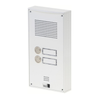
Series 5 and 10 IP
▸
Compact device with integrated speaker and
microphone
▸
One or two call buttons with illuminated
labels
▸
Two freely configurable relays
▸
Tamper contact, freely configurable, can be
used with a safety relay
▸
Codelock function in connection with the
“keypad” module (optional)
▸
Fingerprint sensor in connection with the “Fin-
gerprint” module (optional)
▸
RFID card reader in connection with the “Card
Reader” module (optional)
 Loading...