Do you have a question about the Teledyne 3350 and is the answer not in the manual?
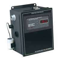
Introduces the Model 3350 Oxygen Alarm Monitor and lists its main features.
Details the front panel components including membrane switches, digital meter, and alarm indicator LED.
Explains data entry buttons, LED display modes, and rear panel connectors for the AC version.
Illustrates DC rear panel connectors and describes power and signal connections for both versions.
Explains oxygen analysis, calibration gas, and the basic working principles of the Micro-Fuel Cell.
Details the construction of the Micro-Fuel Cell, including its inert plastic housing, permeable membrane, anode, and cathode.
Explains the chemical reactions and how pressure changes affect oxygen diffusion and instrument output.
Explains the linear relationship between oxygen concentration and cell output, noting the absolute zero.
Describes the system electronics, including the microcontroller, and illustrates the signal processing path.
Explains how alarm setpoints trigger relay contacts and details factory settings for CAUTION and DANGER alarms.
Lists the steps for installation and provides crucial cautions regarding the Micro-Fuel Cell and its electrolyte.
Details wall-mounting requirements and step-by-step instructions for installing the Micro-Fuel Cell.
Illustrates AC connectors and details primary AC power input, fuse block, and switch.
Shows DC power connections, battery backup function, and system operation during outages.
Guides battery testing, explains service life factors, and details how to connect the rechargeable battery.
Describes analog output signals (0-10V, 4-20mA, Range ID) and the optional RS-232 serial port.
Specifies required RS-232 settings and details the three alarm relay contacts (Form C).
Details alarm types, sensor receptacle, and the initial calibration procedure using ambient air.
Provides detailed calibration steps and introduces the instrument's continuous monitoring function.
Details the 12-month warranty for the Class B-3 cell and provides a safety checklist for verification.
Explains the purpose and design of the flow-through adapter for piped-in gas applications.
Describes the SPAN button and UP/DOWN data entry buttons for calibration and parameter adjustment.
Details preset alarm levels and introduces the need for routine calibration using ambient air.
Provides detailed calibration steps and methods to exit or reset the span procedure if initiated incorrectly.
Outlines general maintenance and detailed steps for replacing fuses in the standard AC version.
Details fuse replacement for battery backup units and indicators for when a sensor needs replacement.
Provides guidelines for ordering, handling spare sensors, and safe removal of spent Micro-Fuel Cells.
Guides installation of a new Micro-Fuel Cell and explains the conditions of the cell's 12-month warranty.
Lists detailed specifications for range, sensitivity, accuracy, response time, operating conditions, and outputs.
Provides lists of spare parts for AC and DC versions and details how to order replacement parts.
Lists available reference drawings and explains symbols and notes related to the instrument.
Provides product identification, manufacturer details, and physical/chemical properties of Micro-Fuel Cells.
Details potential fire/explosion hazards, reactivity, exposure routes, limits, and health effects of Micro-Fuel Cells.
Outlines first aid for exposure and guidelines for handling cell leaks and disposal.
| Brand | Teledyne |
|---|---|
| Model | 3350 |
| Category | Measuring Instruments |
| Language | English |