Do you have a question about the Teledyne WIRELESS GROUNDLINK WQAR and is the answer not in the manual?
Provides an overview of the Teledyne Controls Wireless GroundLink® Quick Access Recorder (WQAR).
Details the functions of the WQAR and the structure of the operations guide.
Explains how the WQAR records and transmits flight data wirelessly using cellular technology.
Explains the WQAR's support for Bi-Polar and Harvard Bi-Phase aircraft signaling types and speed detection.
Describes how WQAR records ARINC429 data (ACMS reports) and the recording completion delay (RCD).
Details High Reliable RF Interlocks for compliance with regulations prohibiting transmission while aircraft is airborne.
Explains the location and function of the RSM, including SIM card installation and OPC files.
Describes WQAR data transmission using 3G/4G networks and operator controls for roaming zones.
Details the WQAR's restriction to a maximum of 3 simultaneous transmissions on band 30.
States WQAR compliance with FCC RF exposure limits and installation guidelines.
Details the WQAR's boot-up sequence, status indicators, and readiness for operation.
Describes how the WQAR records ARINC 717 and report data during flight and saves it to a CF card.
Explains WQAR behavior after landing, including RF interlocks, RCD, data compression, and transmission to WGCM.
Discusses software components (OPS, OPC) and their associated part numbers.
Explains Teledyne Controls' convention for assigning software part numbers, typically 6-digit numbers starting with 7.
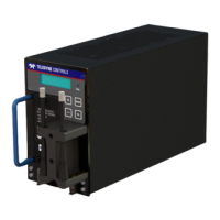
Describes the WQAR's front panel interface for status checks, diagnostics, and maintenance activities.
Explains the blue backlit display, its character limits, and how it shows operational and boot-up status.
Details the amber-colored FAIL indicator which illuminates for hardware faults, missing config files, or full data card.
Explains the function of the MODE, SEL, PLUS, and MINUS buttons on the WQAR's front panel.
Describes the access door, its label, and the components located behind it, including RSM and CF card.
Details the two antennas, their connection, and security, with notes on replacement parts.
Explains the WQAR's system clock (UTC), its power source, and how it is updated.
Describes how to access WQAR menus via front panel buttons and the default SYSTEM STATE display.
Details the WQAR menus, including SYSTEM STATE and UNIT INFO sub-menus.
Describes the SYSTEM STATE menu, which displays the current status of the unit after boot-up.
Explains the UNIT INFO menu and its sub-menus for displaying and changing basic settings.
Details the BOX INFO menu, showing part numbers, serial numbers, and MAC/hardware addresses.
Explains the S/W VERSION menu, which displays Boot and OPS software part numbers.
Allows display of current hardware status, with sub-menus for Acquisition, Discretes, RF IL Ln/Sel, and Wireless.
Displays flight data status including RAW frames, RATE (WPS), SOURCE type, and MESSAGE presence.
Shows status of incoming discretes like INTERLOCK, RUN CONTROL, BIPHASE SELECT, and SPEED SELECT.
Displays the status of each RF Interlock and RF Interlock Select wire pair.
Shows wireless transmission status, unavailable if RF Interlocks are engaged.
Allows operator to perform testing, including DISPLAY TEST, ACQ SIMULATION, RF INTERLCK TEST, and DISCRETE TESTS.
Generates test patterns on the front panel display to verify functionality.
Tests LRU data recording and sending by generating test data at configured WPS speed.
Tests the LRU's RF Interlock circuitry; radios are disabled during this test.
Allows activation and deactivation of outgoing discretes like MEDIA LOW and FAIL.
Tests transmission to Base Station using cellular radios; uses test files, not actual flight data.
When selected, the WQAR will reboot and perform the ARINC717 test.
Temporarily disables radios, preventing diagnostic tests, persistent through power cycles.
Re-enables radios previously disabled; requires a reboot for changes to take effect.
| Brand | Teledyne |
|---|---|
| Model | WIRELESS GROUNDLINK WQAR |
| Category | Measuring Instruments |
| Language | English |