Do you have a question about the Teledyne 2000A-EU and is the answer not in the manual?
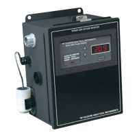
Describes the controls and display elements on the front panel of the analyzer for operation.
Explains the principles of the thermal conductivity sensor and its operation using a Wheatstone bridge.
Explains the necessity and basic steps of calibrating the analyzer using known gases to set range parameters.
Details the rear panel layout and connectors for power, digital communications, and analog outputs.
Explains how to connect the power source and the function of the standby switch.
Describes the pin layout and functions of the 50-pin equipment interface connector for various outputs.
Details the alarm relay contacts, their configuration modes (latching, failsafe), and terminal connections.
Outlines the pre-power up checks and initial system testing procedures before powering on.
Describes the normal operating mode for monitoring sample gas concentration and alarms.
Guides the user through configuring and initiating automatic calibration cycles for zero and span.
Instructions on how to initiate the instrument's self-diagnostic routine and interpret failure codes.
Detailed steps for performing zero calibration in automatic or manual modes to establish a baseline.
Detailed steps for performing span calibration in automatic or manual modes to set the upper calibration limit.
Explains how to configure concentration and system failure alarms, modes, and setpoints.
Procedures for reprogramming analyzer settings like range and algorithm via RS-232 or front panel.
Instructions on how to initiate the instrument's self-diagnostic routine and interpret failure codes.
Procedures for replacing the thermal conductivity cell, heater, or thermistor, starting with compartment removal.
Step-by-step guide to calibrate Range 1 of the analyzer using zero and span gases.
Step-by-step guide to calibrate Range 2 of the analyzer using zero and span gases.
Step-by-step guide to calibrate Range 3 of the analyzer using zero and span gases.
Step-by-step guide to calibrate the calibration range (Cal Range) for the analyzer.
| Brand | Teledyne |
|---|---|
| Model | 2000A-EU |
| Category | Measuring Instruments |
| Language | English |