Do you have a question about the Teledyne 200E and is the answer not in the manual?
Details on the different formats in which the M200E instruction manual is available.
Overview of the manual's structure, including sections, figures, and tables.
Guidance on interpreting manual conventions, including text formatting and flowcharts.
Lists the analyzer's performance specifications, operating conditions, and EPA equivalency.
Details the M200E's designation as Reference Method Number RFNA-1194-099 by the EPA.
States compliance with various EMC and safety standards, including EN61326 and EN61010-1.
Outlines T-API's warranty policy, coverage, and terms for manufactured equipment.
Instructions for safely unpacking the analyzer, inspecting for damage, and initial setup.
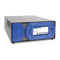
Diagrams and descriptions of the analyzer's internal components and rear/front panel layout.
Details on connecting gases and exhaust lines, including safety precautions.
Instructions for power connection, analog output, status output, and control input connections.
Procedures for starting up the analyzer, including warm-up and initial functional checks.
Step-by-step guide for performing the initial calibration of the M200E analyzer.
Answers to common questions regarding analyzer operation, calibration, and troubleshooting.
Definitions of acronyms and technical terms used throughout the manual.
Description and part numbers for external pumps available for the M200E series analyzers.
Options for mounting the analyzer in standard 19-inch racks.
Details on the isolated voltage-to-current conversion circuitry for analog outputs.
Information on the particulate filter kit, including quantity and specifications.
Describes the zero/span valve and internal zero/span (IZS) options for calibration gas control.
Details on charcoal scrubbers, zero air scrubbers, and related maintenance kits.
Overview of communication options including RS232, Multidrop, and Ethernet.
Description of the analyzer's various operating modes: SAMPLE, SETUP, and CAL.
Details on the analyzer's standard operating mode for analyzing NO, NOX, and NO2 concentrations.
Information on the calibration mode, including its importance and description in Chapter 7.
Guidance on using the SETUP mode to configure analyzer features and the iDAS system.
Configuration of analog output signals, including physical and reporting ranges.
Explanation of user-adjustable software variables defining operational parameters.
Details on diagnostic tools available for troubleshooting and maintenance.
Description of status outputs and control inputs for interfacing with external devices.
Configuration of the analyzer's serial communication ports (COM1 and COM2).
Information on the internal data acquisition system (iDAS) for storing data and diagnostics.
Guidance on remotely configuring, calibrating, and querying the analyzer.
Details on required equipment, supplies, and initial setup for calibration.
Step-by-step instructions for manually calibrating the analyzer.
Procedures for performing informal calibration checks to monitor analyzer performance.
Method for manual calibration and checks with zero/span valve option installed.
Procedure for calibrating with the IZS option, including CAL_ON_NO2 feature.
Performing manual calibration checks with IZS or zero/span valve options.
Additional considerations for calibrating with AUTO or IND reporting ranges.
Details on the AutoCal feature for unattended, periodic calibration operations.
General calibration process, emphasizing traceable standards and dynamic calibration.
Principle of operation, calibrator check procedure, and calculations for GPT.
Procedure for multipoint calibration using GPT, including software feature settings.
Recommended preventive maintenance schedule for the M200E analyzer.
Using test functions to predict failures and track instrument trends.
Step-by-step procedures for performing regular maintenance tasks on the analyzer.
Explanation of the chemiluminescence measurement principle for NO, NOX, and NO2.
Description of the analyzer's pneumatic systems, including pumps, valves, and sensors.
Overview of the analyzer's electronic components and their functions.
Systematic approach and initial steps for identifying and resolving analyzer problems.
Troubleshooting steps for issues related to sample, ozone, and other gas flows.
Common calibration issues and their potential causes and solutions.
Troubleshooting dynamic problems that manifest during sample gas monitoring.
Procedures to verify the functionality of individual analyzer components and subsystems.
Detailed procedures for replacing major analyzer components.
Contact information and procedures for obtaining technical support from Teledyne-API.
Graphical representation of the analyzer's software menu structure and an index.
List of individual spare parts for the M200E analyzer with part numbers and notes.
Recommended stocking levels for spare parts based on the number of analyzers.
List of expendable items and kits, including quantities for replacement.
Section to list any error or warning messages displayed on the front panel.
Table for recording recorded and acceptable values for various test parameters.
Index of all diagrams and schematics included in the appendix.
| Technology | Chemiluminescence |
|---|---|
| Accuracy | ±1% of full scale |
| Resolution | 0.1 ppb |
| Power Supply | 100-240 VAC, 50/60 Hz |
| Type | Gas Analyzer |
| Operating Temperature | 5°C to 40°C |
| Outputs | RS-232 |