Do you have a question about the Teledyne 440 and is the answer not in the manual?
Highlights improvements of the 440 System over the 340 system, including greater range and simpler operation.
Explains the conventions used in the manual for warnings, cautions, and notes.
Provides an overview of the 440 System, its components, and primary applications.
Details the 'Pulse Induction' principle and its advantages for pipe and cable surveys.
Outlines the warranty terms and conditions for the 440 Pipe and Cable Survey System.
Provides contact information for product support and additional information resources.
Guide for initial unpacking, inspection of components, and precautions against damage.
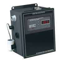
Detailed description of the surface components, including the SDC10.
Overview of the sub-sea components: SEP, PSU, search-coils, and altimeter.
Instructions for installing the SDC, including location choice and ventilation.
General guidance for installing the sub-sea components and ensuring data accuracy.
Instructions for installing the Sub-sea Electronics Pod (SEP) and Power Supply Unit (PSU).
Details on assembling and mounting the search-coil array onto the ROV.
Guidance on installing the sub-sea altimeter for accurate depth of cover measurements.
A comprehensive checklist for verifying the physical installation of the system.
Instructions for completing the electrical installation of the sub-sea components.
Details on connecting the SDC, including power and communication links.
Procedure for connecting AC electrical power to the SDC unit.
Explanation of communication link setup between the SEP and SDC.
Guidance on connecting the SDC to an external data logger for survey recording.
Instructions for video input and output connections on the SDC.
Details on configuring and using the SDC10 analogue outputs.
Step-by-step instructions for powering on the system and launching DeepView.
Procedure for initial software configuration, including SEP type and communication ports.
Setting the SEP type (No SEP, 440, or Dualtrack) for system configuration.
Configuration of serial communication ports for SEP, altimeter, and data logger.
Setting key system parameters like target scaling, threshold, and seawater compensation.
Instructions for printing system configuration details for survey logs.
Guide to using the DeepView software for system operation and survey control.
Description of the commands available in the DeepView Menu Bar.
Details on accessing and using various windows within DeepView for data display.
Options for configuring system parameters, altimeter, and external outputs.
Explanation of the command buttons on the DeepView for Windows toolbar.
List and explanation of function keys for controlling DeepView operations.
Tasks to perform after completing a survey, including printing and powering down.
Instructions for replaying logged data files using the DeepView software.
Explanation of the Quality Control function and how it indicates data accuracy.
Steps for recovering the system if it fails to operate correctly.
Instructions for reinstalling the DeepView for Windows software.
Guide for installing DeepView for Windows software on a separate PC.
Planning steps before a survey, including system suitability and personnel availability.
Essential mechanical, electrical, and configuration checks before system deployment.
Checks related to the mechanical installation and depth rating of sub-sea components.
Checks for correct power supply and cable connections for sub-sea components.
Guidance on using the 440 System correctly during actual survey operations.
Steps to configure the system for a survey, including target scaling and parameters.
Performing functional checks on coils, target detection, oscilloscope, and altimeter.
Procedures for background compensation to ensure accurate measurements.
Method for distinguishing target signals from seawater signals using calibration parameters.
Measuring spurious signals to assess their effect on survey data quality.
Using the Run Display screen and other features during the survey operation.
Importance of maintaining a full log of events and data during the survey.
Instructions for replaying logged data files using DeepView for Windows.
Using acquired data to plot additional information and modify target profile appearance.
Plotting target profiles with data including coordinates, signals, and quality control.
Procedure for determining target scaling factor using Auto Scaling or manual entry.
Details on data formats and RS232 parameters for various compatible altimeters.
Factors influencing system response and performance, including target characteristics and coil arrangement.
Identification of error sources that can degrade system performance.
Potential sources of error arising from unskilled ROV operation and positioning.
Description of interference sources that might affect the 440 System.
Considerations for using the 440 System with different types of ROVs.
Detailed specifications for the 440 System and its major assemblies.
Technical specifications for the SDC10 unit.
Technical specifications for the Sub-sea Electronics Pod (SEP).
Technical specifications for the Sub-sea Power Supply Pod (PSU).
Technical specifications for the search coil array components.
Results of performance tests illustrating range and accuracy under ideal conditions.
Information on setting the system's data update rate for external logging.
Description of the main internal components of the sub-sea installation.
Details on the PSU's PCB assembly and filter network.
Description of the SEP's circuit boards: Main, Driver, and Analogue boards.
Explanation of the 2-wire current-loop communications method.
Procedures for safely disassembling and reassembling system components.
Precautions and steps for disassembling the Surface Display Computer.
Procedures for disassembling sub-sea pods, including SEP and PSU.
Advice and flow charts for locating faults within the sub-sea components.
Troubleshooting flowchart for faults affecting only a single channel.
Troubleshooting flowchart for current loop communication failures.
Troubleshooting flowcharts for identifying and resolving altimeter failures.
Troubleshooting for unexpected signal variations during normal system operation.
List of available electrical drawings for system components.
List of available mechanical drawings for system components.
Explanation of the Pulse Induction method used for target detection.
Details on how the system measures range using decaying voltage waveforms.
Explanation of the timing considerations during each measurement cycle.
How signal voltages are derived from measurements for channel calculations.
Advances in signal processing for discriminating seawater from metallic targets.
Explanation of background and active compensation methods for signal processing.
Considerations for survey information on crawling ROVs where lifting is not possible.
Discussion of system limitations, including target lift curves and seawater effects.
Method for determining target range based on coil signals and scaling factors.
Description of the Dualtrack system combining 440 and 350/350 Powertrack systems.
List of equipment included in the Dualtrack system configuration.
Highlights important issues and differences when installing the Dualtrack System.
Details the standard sub-assemblies included with the Dualtrack system.
Specific precautions for physical installation of the Dualtrack system on an ROV.
Information on the three sub-sea pods included in the Dualtrack system.
Critical instructions for interconnecting sub-sea components in a Dualtrack system.
Steps to configure the Dualtrack system using DeepView's System Configuration Wizard.
How the SDC operates with Dualtrack system software after power-on.
Availability of the Forward Search Window for 350 and Dualtrack options.
Details on power supply requirements for Dualtrack system sub-sea components.
Information on Teledyne TSS training courses for the 440 System.
Sample form for recording target details and background compensation data.
Sample form for recording results from automatic and optimized target scaling.
Sample form for recording VRT values displayed by SDC based on lateral offset.
Log sheet for recording essential details about each survey.
Form for recording all system configuration parameters for a survey.
| Brand | Teledyne |
|---|---|
| Model | 440 |
| Category | Measuring Instruments |
| Language | English |