3 – Physical Installation
DPN 402196 Issue 4.1 © Teledyne TSS 3- 3
Installing in 19” instrument rack
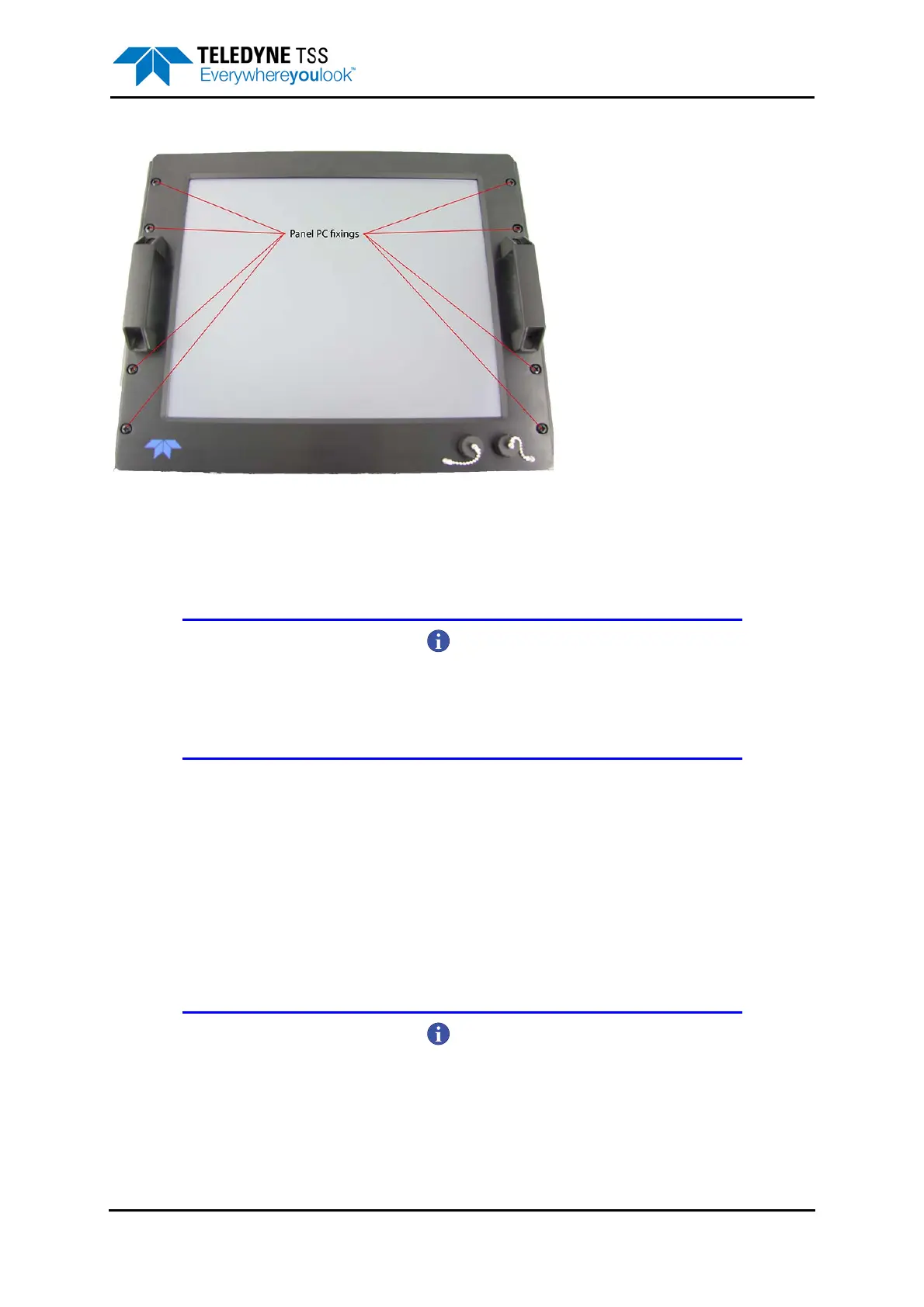
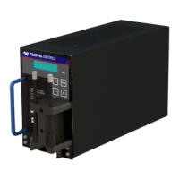
Figure 3-2: SDC10 - Panel PC fixings
1. Open the four fixings located on the front and rear of the transit case (Figure 3-1).
2. Remove the 8 x Panel PC fixing screws securing the SDC10 to the angled brackets fixed to the
transit case base.
NOTE
If you intend to change the analogue output configuration used by the 440 Sys-
tem, make the necessary changes to the SDC before you install it into the instru-
ment rack. Refer to sub-section 4.2.5.2 "Analogue Output DIP Switch Settings”
beginning on page 4-17 for instructions to change the analogue output settings.
3.1.1 Sub-sea Installation
The care that you take when you install the sub-sea components of the 440 System will have a
significant influence on the accuracy of survey data. Read the following instructions carefully and
ensure that you have all the necessary parts and tools available before you attempt to install the
System.
3.1.2 SEP and PSU
NOTE
Do not open either pod during the installation procedure unless you need to
change the communication method used by the System. See section 4.2.2.1
"Alternative Communication Methods" on page 4-11 for instructions to change the
communication method. You do not need to open the PSU to change the commu-
nication method.




 To Next Page