3 – Physical Installation
DPN 402196 Issue 4.1 © Teledyne TSS 3- 9
All fastenings, for example cable clips and screws, must be non-conductive.
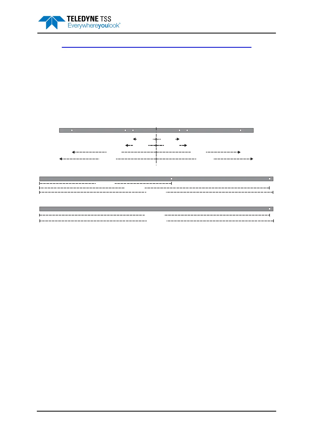
The System includes three pairs of pre-drilled nylon beams to support the coils on the ROV. Figure 3-5
shows each type of nylon supporting beam:
❐ Two coil mounting strips
❐ Two outriggers
❐ Two tie-bars
Figure 3-5: Components of the coil frame
Figure 3-6 shows how to construct the coil frame.
2160mm
2130mm
1290mm
240mm
390mm 390mm
240mm
870mm 870mm
900mm 900mm
2130mm
Tie Bar
Mounting Strip
Outrigger
2160mm





 To Next Page