Operating Instructions Model 200E Instruction Manual
6.7.3.3. Manual Analog Output Calibration
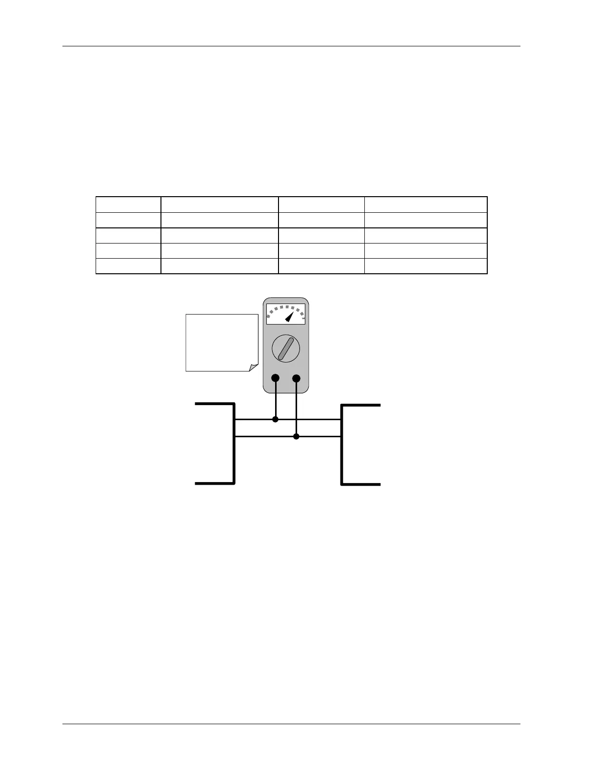
For highest accuracy, the voltages of the analog outputs can be manually calibrated. Note
that outputs configured for 0.1V full scale should always be calibrated manually. Calibration
is done through the instrument software with a voltmeter connected across the output
terminals (Figure 6-3). Adjustments are made using the front panel keys by setting the
zero-point first and then the span-point (Table 6-11). The software allows this adjustment
to be made in 100, 10 or 1 count increments.
Table 6-11: Voltage Tolerances for Analog Output Calibration
Full Scale Zero Tolerance Span Voltage Span Tolerance
0.1 VDC ±0.0005V 90 mV ±0.001V
1 VDC ±0.001V 900 mV ±0.001V
5 VDC ±0.002V 4500 mV ±0.003V
10 VDC ±0.004V 4500 mV ±0.006V
V
+DC Gnd
V OUT +
V OUT -
V IN +
V IN -
Recording
Device
ANALYZE
See Table 3-1 for
pin assignments
of Analog Out
connector on the
rear panel
Figure 6-2: Setup for Calibrating Analog Outputs
To make these adjustments, the AOUT auto-calibration feature must be turned off
(Section 6.7.3). Then press SETUP-MORE-DIAG-ENTR-NEXT-NEXT and the following keys:
64 044100102 Rev A