Operating Instructions Model 200E Instruction Manual
Table 6-15: Control Input Pin Assignments
Input Status Condition when enabled
A
EXTERNAL ZERO
CAL
Zero calibration mode is activated. The mode field of the
display will read
ZERO CAL R.
B
EXTERNAL SPAN
CAL
Span calibration mode is activated. The mode field of the
display will read
SPAN CAL R.
C
EXTERNAL LOW
SPAN CAL
Low span (mid-point) calibration mode is activated. The
mode field of the display will read
LO CAL R.
D Unused
E Unused
F Unused
DIGITAL GROUND Provided to ground an external device (e.g., recorder).
U
DC power for
Input pull ups
Input for +5 VDC required to activate inputs A - F. This
voltage can be taken from an external source or from the
“+” pin.
+
Internal +5V
Supply
Internal source of +5V which can be used to activate
inputs when connected to pin U.
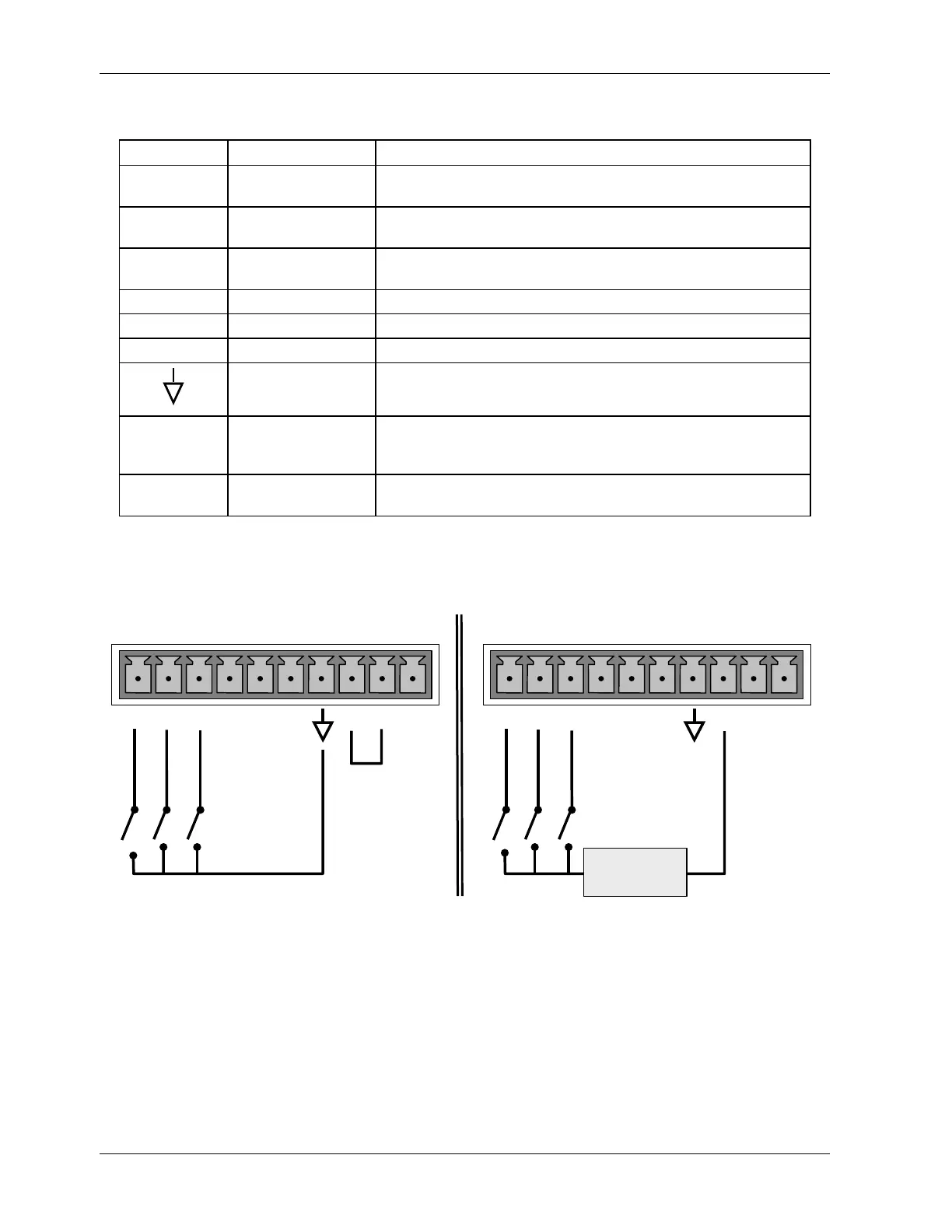
There are two methods to activate control inputs. The internal +5V available from the “+”
pin is the most convenient method (see figure). However, to ensure that these inputs are
truly isolated, a separate, external 5 VDC power supply should be used.
LOW SPAN
ZERO CAL
SPAN CAL
CONTROL IN
Local Power Connections
External Power Connections
LOW SPAN
ZERO CAL
SPAN CAL
CONTROL IN
-
+
5 VDC Power
Supply
A B C D E F U
+
A B C D E F U
+
Figure 6-5: Control Inputs with Local and External 5 V Power Supply
6.9. Setup - Communication Ports (COMM)
The M200E is equipped with two serial communication ports located on the rear panel
(Figure 3-3). Both ports operate similarly and give the user the ability to communicate with,
issue commands to, and receive data from the analyzer through an external computer
system or terminal. By default, both ports operate on the RS-232 protocol. The COM2 port,
74 044100102 Rev A