Model 200E Instruction Manual APPENDIX A
APPENDIX A-4: M200E Signal I/O Definitions, Revision C.8
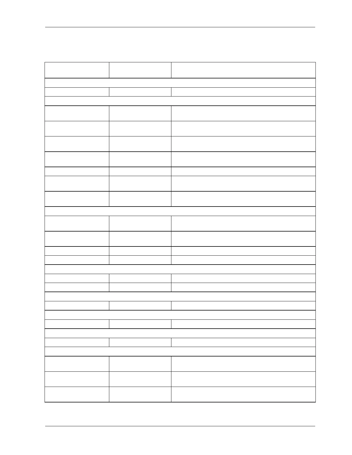
Table A-4: M200E Signal I/O Definitions, Revision C.8
Signal Name Bit or Channel
Number
Description
Internal inputs, U7, J108, pins 9-16 = bits 0-7, default I/O address 322 hex
0-7 Spare
Internal outputs, U8, J108, pins 1-8 = bits 0-7, default I/O address 322 hex
ELEC_TEST 0 1 = electrical test on
0 = off
OPTIC_TEST 1 1 = optic test on
0 = off
PREAMP_RANGE_HI 2 1 = select high preamp range
0 = select low range
O3GEN_STATUS 3 0 = ozone generator on
1 = off
4-5 Spare
I2C_RESET 6 1 = reset I
2
C peripherals
0 = normal
I2C_DRV_RST 7 0 = hardware reset 8584 chip
1 = normal
Control inputs, U11, J1004, pins 1-6 = bits 0-5, default I/O address 321 hex
EXT_ZERO_CAL 0 0 = go into zero calibration
1 = exit zero calibration
EXT_SPAN_CAL 1 0 = go into span calibration
1 = exit span calibration
2-5 Spare
6-7 Always 1
Control inputs, U14, J1006, pins 1-6 = bits 0-5, default I/O address 325 hex
0-5 Spare
6-7 Always 1
Control outputs, U17, J1008, pins 1-8 = bits 0-7, default I/O address 321 hex
0-7 Spare
Control outputs, U21, J1008, pins 9-12 = bits 0-3, default I/O address 325 hex
0-3 Spare
Alarm outputs, U21, J1009, pins 1-12 = bits 4-7, default I/O address 325 hex
4-7 Spare
A status outputs, U24, J1017, pins 1-8 = bits 0-7, default I/O address 323 hex
ST_SYSTEM_OK 0 0 = system OK
1 = any alarm condition
ST_CONC_VALID 1 0 = conc. valid
1 = hold off or other conditions
ST_HIGH_RANGE 2 0 = high auto-range in use
1 = low auto-range
044100110 Rev A 243