Model 200E Instruction Manual Operating Instructions
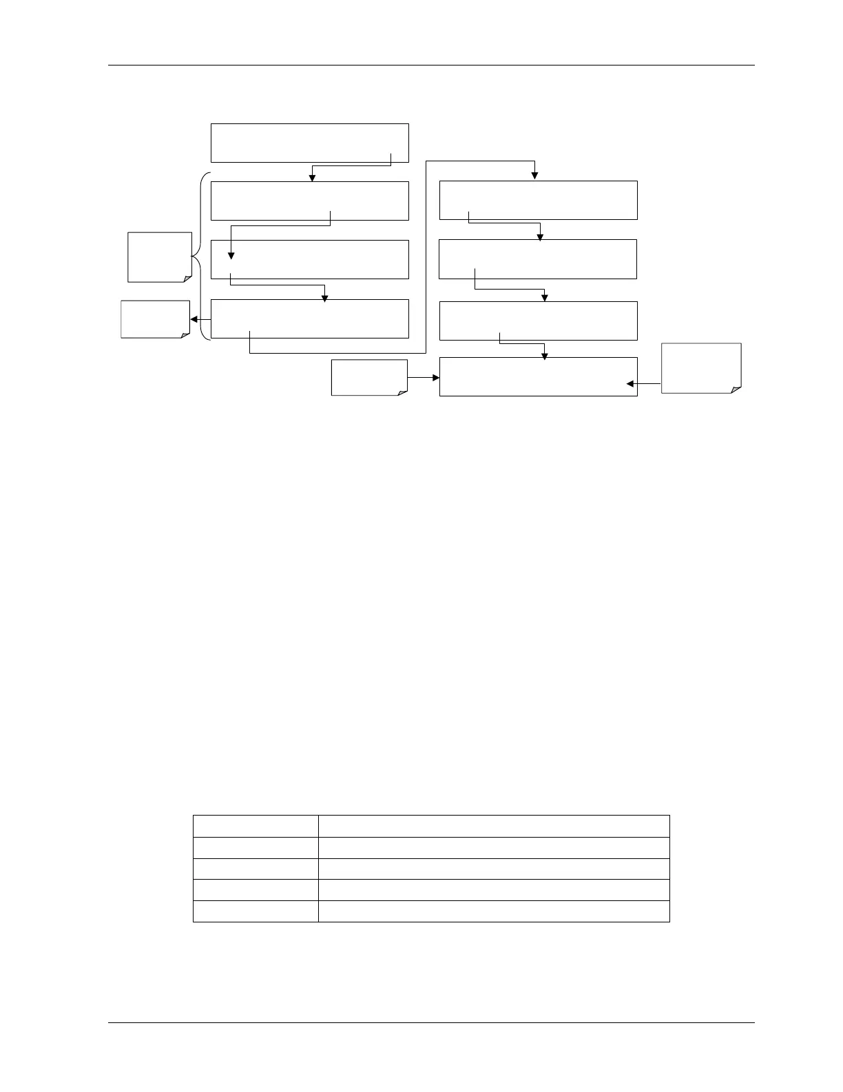
To initiate the test press the following key sequence.
Select which
COM port to
test.
SETUP X.X
PRIMARY SETUP MENU
CFG DAS RNGE PASS CLK MORE EXIT
SETUP X.X
SECONDARY SETUP MENU
COMM VARS DIAG EXIT
SAMPLE RANGE = 500.0 PPB NOX =XXX.X
< TST TST > CAL SETUP
SETUP X.X COMMUNICATIONS MENU
ID
COM1
COM2
EXIT
EXIT returns
to the
previous
menu
SETUP X.X
COM1 : TEST POR
<SET
TEST
EXIT
SETUP X.X
TRANSMITTING TO COM1
<SET
TEST
EXIT
SETUP X.X COM1 MODE:0
SET>
EDIT EXIT
SETUP X.X COM1 BAUD RATE:19200
<SET
SET>
EDIT
EXIT
EXIT returns to
COMM menu
Test runs
automatically
6.9.9. Ethernet Port Configuration
The optional Ethernet port (Section 5.7.3) communicates with the analyzer through the
COM2 serial port. Refer to Figure 3-2 and Figure 5-2 for location of this option. The Ethernet
board has two operational modes:
• Pass-through mode: This is the normal operation mode in which the board actively
passes data between the RS-232 port and the RJ-45 connector on the analyzer’s rear
panel. This enables all remote commands to be passed to the analyzer.
• Configuration mode: The board stops passing data and is ready to accept and store
configuration parameters and firmware upgrades. The use of a terminal window or
separate configuration program is needed for these low-level configuration changes.
The iChip configuration utility is available at http://www.teledyne-api.com/software/
and provides a convenient, graphical user interface, which runs only on Microsoft
Windows
TM
operating systems. All commands can also be issued via Terminal window
using the
AT+i protocol. Instructions for AT+i commands are also available at the
website along with other pertinent information.
The Ethernet board has four LEDs that are visible on the rear panel of the analyzer,
indicating its current operating status (Table 6-18).
Table 6-18: Ethernet Status Indicators
LED Function
LNK (green) ON when connection to the LAN is valid.
ACT (yellow) Flickers on any activity on the LAN.
TA (green) Flickers when the RS-232 port is transmitting data.
RA (yellow) Flickers when the RS-232 port is receiving data.
As soon as the Ethernet option is enabled in the COMM menu, a new sub-menu INET will
appear. This sub-menu is enabled by default when the analyzer was ordered with built-in
Ethernet and is used to set configuration parameters that enable the Ethernet card to
044100102 Rev A 81