Model 200E Instruction Manual Theory of Operation
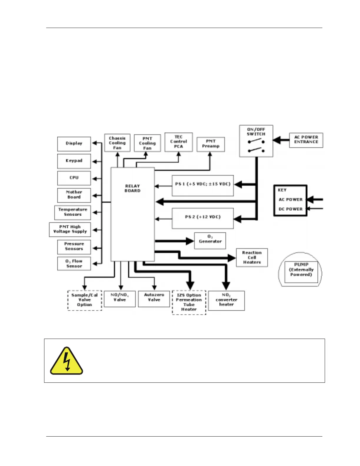
of the instrument. From there, it is routed through the ON/OFF switch located in the lower
right corner of the front panel and back to the relay board, which carries the switching
power supplies.
AC line power is stepped down and converted to DC power by two switching power supplies,
one for +12 VDC (5 A) for various valves and the TEC, and a second supply that provides
+5 VDC (3 A) and ±15 VDC (1.5/0.5 A) for logic and analog circuitry as well as the ozone
generator. All AC and DC Voltages are distributed through the relay board. A 5 ampere
circuit breaker is built into the ON/OFF switch. In case of a wiring fault or incorrect supply
power, the circuit breaker will automatically turn off the analyzer. Under normal operation,
the M200E draws about 1.5 A at 115 V and 2.0 A during start-up.
Figure 10-15: Power Distribution Block Diagram
CAUTION
Should the power circuit breaker trip correct the condition causing
this situation before turning the analyzer back on.
10.3.7. Communications Interface
The analyzer has several ways to communicate with the outside world as shown in Figure
10-16. Users can enter data and receive information directly through the front panel keypad
044100102 Rev A 181